The number of cloud-based applications for the AEC industry has been steadily rising since cloud computing was introduced over a decade ago, but so far, most of these applications have been for tasks such as project management, collaboration, model-checking, issue management, and construction planning (for example, see the reviews of Aconex, Skysite, BIM Assure, and TonicDM)—tasks that deal primarily with content that has been already created. Applications that actually allow you to author design content using a web browser are few and far between, and even those that exist are primarily desktop applications that have been extended to work on the web, such as SketchUp and AutoCAD. This is why when I came across Infurnia, I was intrigued, because it was developed from the ground up as a cloud-based design application. There is no desktop version and nothing that needs to be installed for it to work.
So how well does it actually work? Let’s find out.
Infurnia comes from a startup company based in India that started developing its cloud-based application for architecture and interior design in January 2016. The vision was to be able to create as well as collaborate on a design, in a manner similar to how Google Docs works for documents. In addition, the design would be created using intelligent building objects rather than generic 2D or 3D entities, making it more of a BIM rather than a CAD application. In fact, Infurnia works in a manner very similar to Revit. The scope of the application is currently limited to residential design and the detailed interior design of the spaces that exist within a typical house or apartment.
In addition to being easy to use and access, the main objective of making the application web-based was to allow architects and designers to easily work together on a design as well as share their work with their customers and collaborate with them in real-time. It includes some very innovative features in addition to co-designing, such as the ability to create parallel branches of a design that other designers can work on independently, and at the end, being able to merge these branches back together to get the final design. There is also a follow-along capability that not only allows a client to see the design in real-time but follow the actions of the designers as they navigate the design or make changes to it. The follow-along capability works in reverse as well, allowing the designer to follow the client as they navigate the design and discuss it.
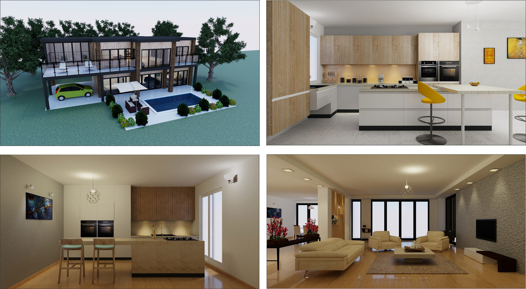
Critical to any design application is the ability to create photorealistic renderings of the design concept, and Infurnia does this by integrating a cloud-based rendering service with the application. Some of the renderings produced by it are shown in Figure 1.
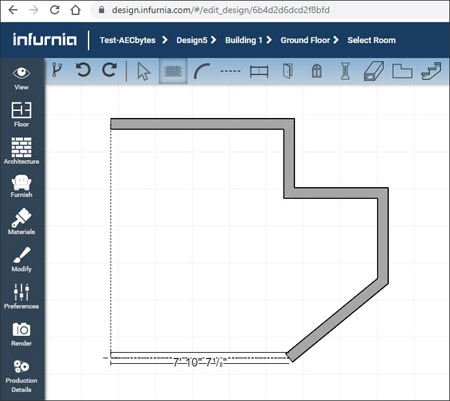
Once you sign into Infurnia, you can choose to continue working on an existing design or create a new design, which can be blank or based on an existing template. First-time users would typically start out with a blank design to see how it works. You are automatically taken to the Ground Floor of a default building and can start creating the floor plan with walls. Figure 2 shows walls being created with the Straight Walls tool. Similar to Revit, there is a heads-up dimension display to act as a guide, along with temporary dotted lines to indicate alignment, making it easier to create walls of the required dimensions.
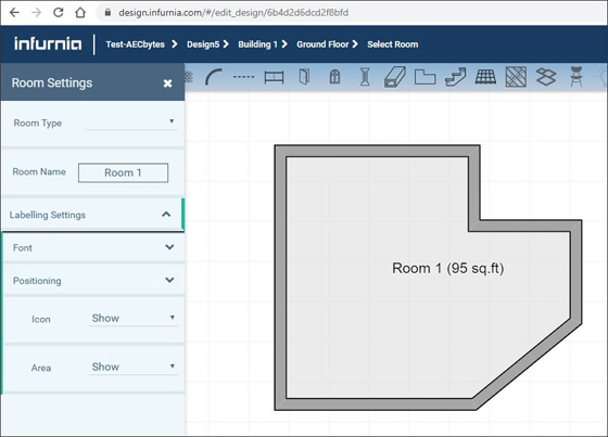
Once a set of walls is closed, a room is automatically detected and labelled (Figure 3). The settings for the room, such as its name and label display, can be accessed and modified in the side palette that opens up by double-clicking on it. This works for all the entities in the model—so, for instance, double-clicking on a wall allows its parameters such as height, dimensions, type, construction layers, etc., to be specified as required.
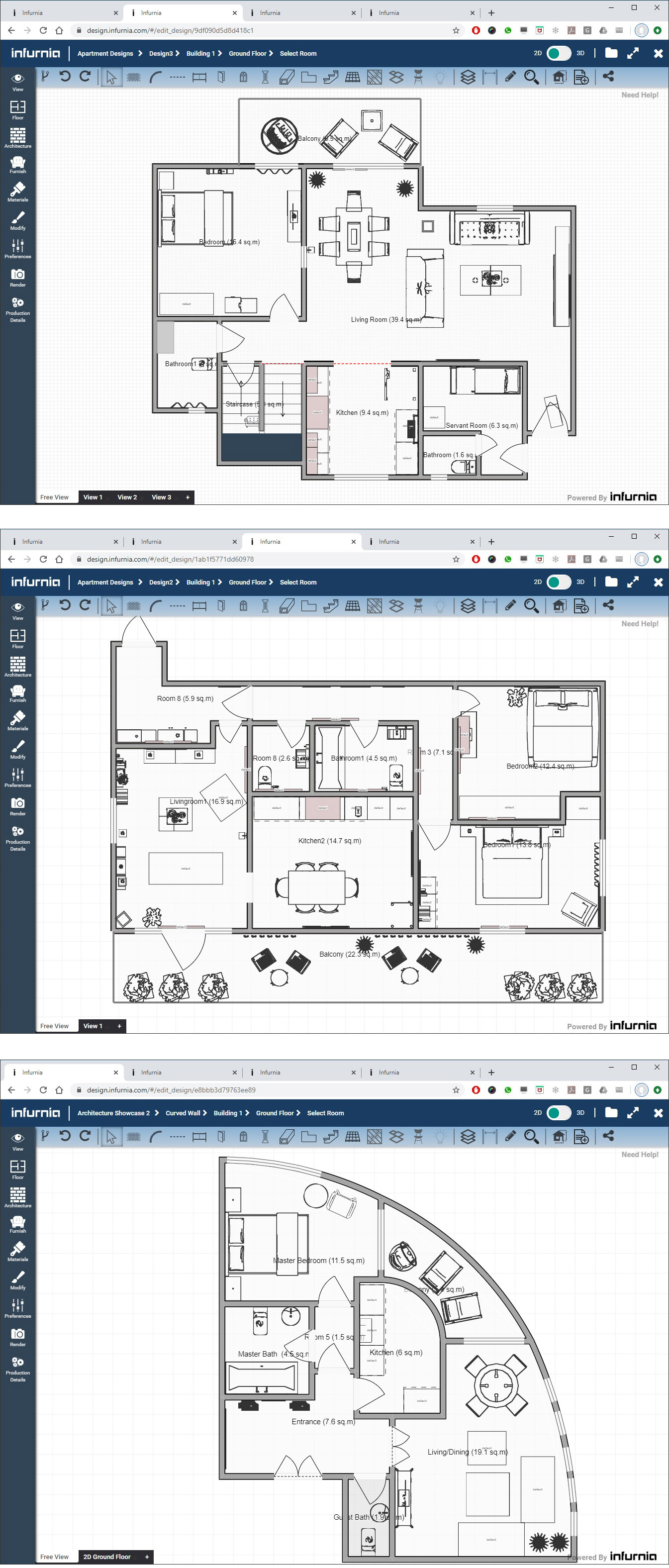
In addition to straight walls, you can also create curved walls, room dividers, balcony walls or railings, and boundary walls or fences, all of which automatically create rooms when they create an enclosure. A few examples of completed floor plans incorporating these different types of wall elements are shown in Figure 4. The full interface of the application can also be seen in these images.
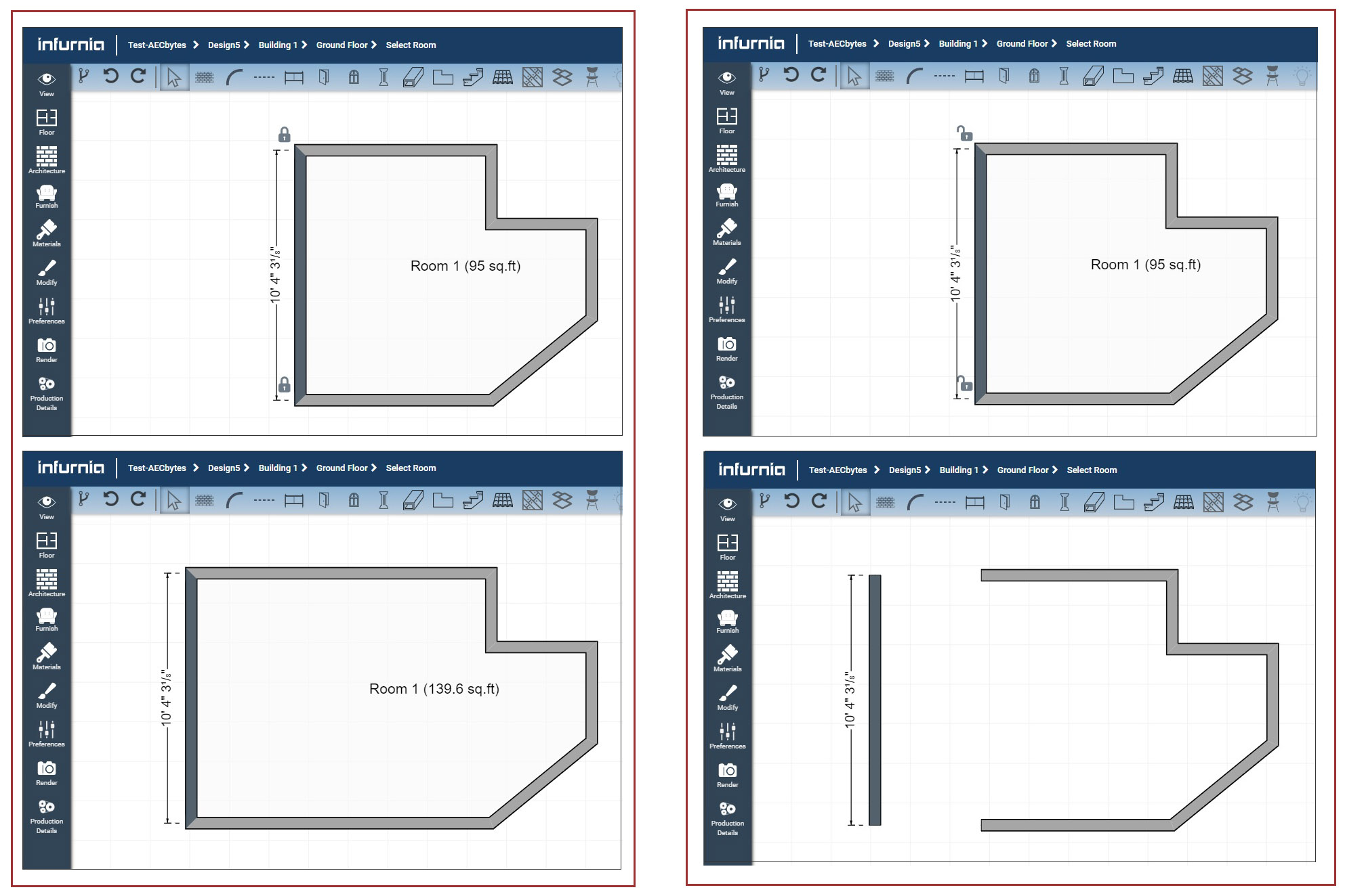
Getting back to the simple example shown in Figure 2, if the position of a wall is modified, the neighboring walls are automatically stretched to maintain the connection unless the Lock icon is deselected, in which case a wall can be moved without affecting the adjoining walls. This is shown in Figure 5. In the first case, shown on the left, the room area is automatically updated, whereas in the second case, shown on the right, the room is automatically deleted since the walls no longer enclose a space.
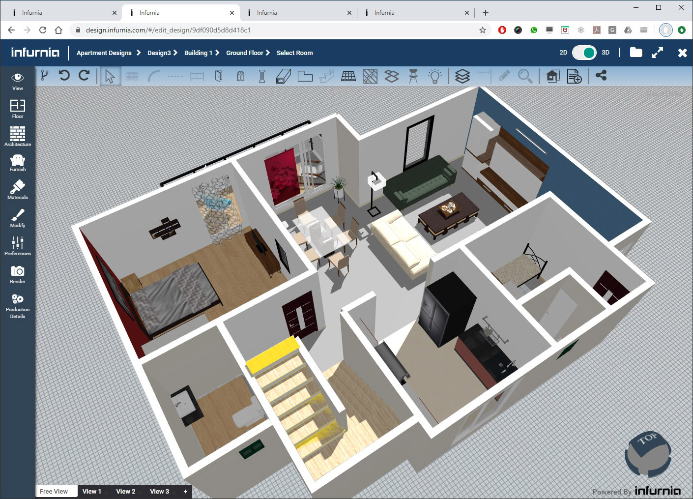
The view can be toggled between 2D and 3D at any time. The 3D view of one of the completed designs from Figure 4 is shown in Figure 6. Mouse controls can be used to zoom, pan, and orbit the view, and multiple views can be saved for easy navigation using the tabs at the base of the graphics window. While the Wall tool is not active in the 3D mode—walls can only be created in 2D—all other tools are active, allowing doors and windows to be inserted in walls, as well as columns, beams, and slabs to be created in 3D.
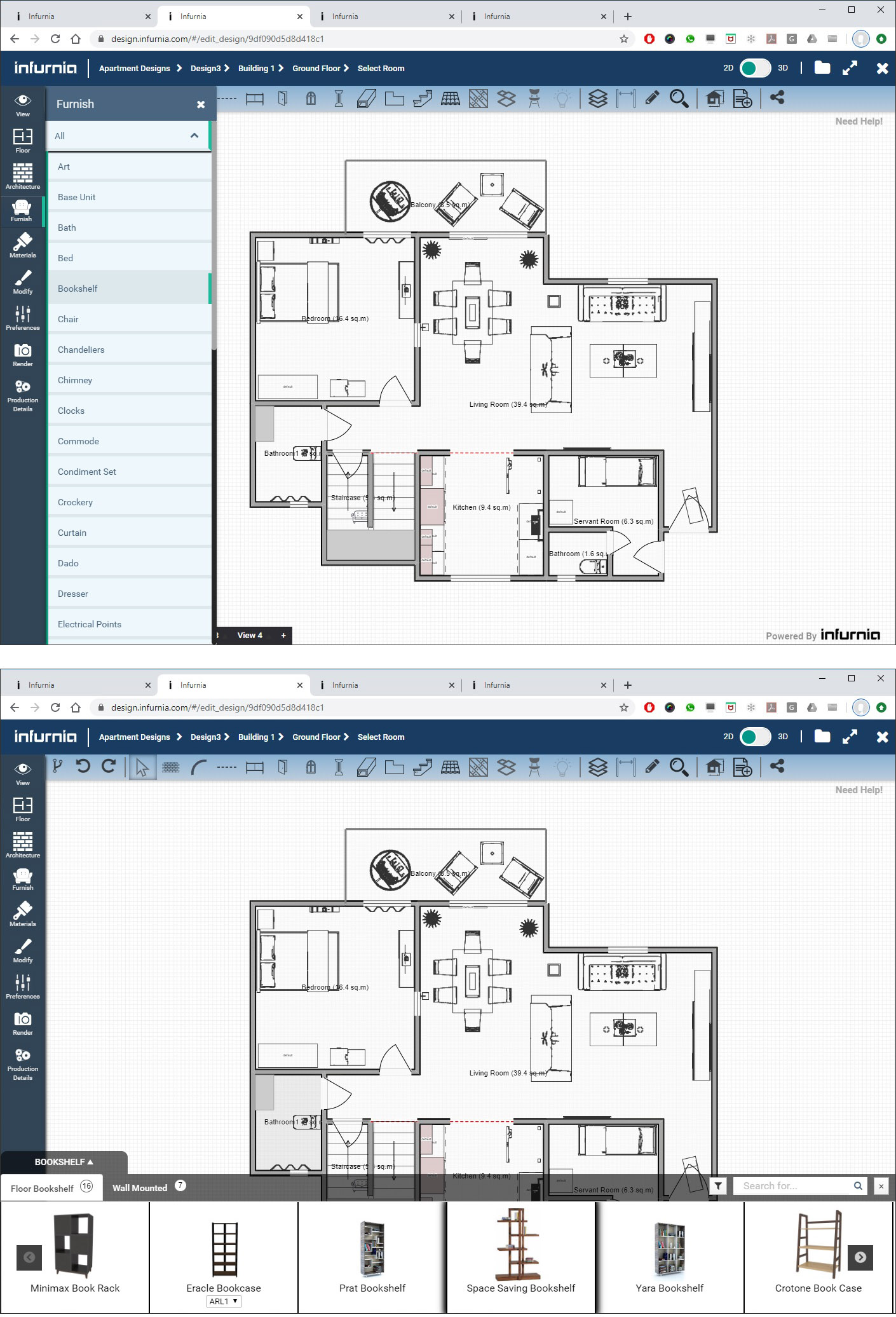
In addition to adding doors and windows to walls, there are tools for placing beams and columns (called pillars), creating floor and ceiling slabs, adding tiling, as well as a comprehensive roof module. Also, since this is a full-fledged interior design application as well, you can furnish the design with a wide range of objects that are most commonly used in residential design (Figure 7). Selecting an object type loads the available objects of that type in a “carousel” from where they can be selected and added to the design. This carousel-selection is also implemented for objects such as doors, windows, columns, railings, etc.
All of these interior design objects are not only based on real-world products, but they can also be customized to a high level of granularity. So, for example, all the different individual components that make up a cabinet unit placed in a kitchen can be customized, including the number of drawers, the material and configuration of each drawer, the type of handles, the door panel, and so on (Figure 8). There is even an option to open and close the doors or drawers of a cabinet! The objects are “smart” to the extent that they can be placed without overlapping with each other, and they can also “stick” to the specified surface. Thus, most of the furniture sticks by default to the floor and can be moved along it, which is especially handy when it is being placed in a 3D view. On the other hand, objects such as lighting fixtures can be specified to stick to walls or ceilings.

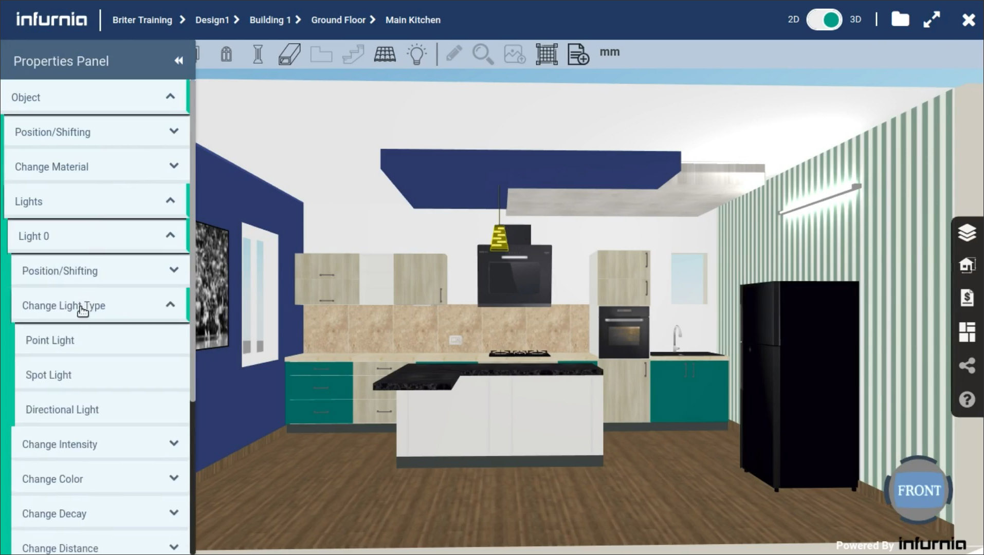
The lighting fixtures are especially important for renderings, and in addition to placing different kinds of fixtures in a room—on walls, ceilings, floors, or stand-alone—you can also specify the type of light, its intensity, color, etc. (see Figure 9). The intensity of ambient light can also be adjusted. For the actual rendering, while some of the presentation quality renderings generated from the application were shown in Figure 1, there are also options to generate medium quality renderings, which take about 2 minutes for a scene and can be used to test the design iteratively before finalizing it. Medium quality renderings are also done using the separate rendering service, which means the designer can continue using the application after issuing the Render command. As an alternate to using the rendering service, you can also export the scene to a blend file and render it yourself in Blender, which is a free and open-source rendering application. Also, in addition to rendering a single scene, you can choose to render a panoramic view or VR view.
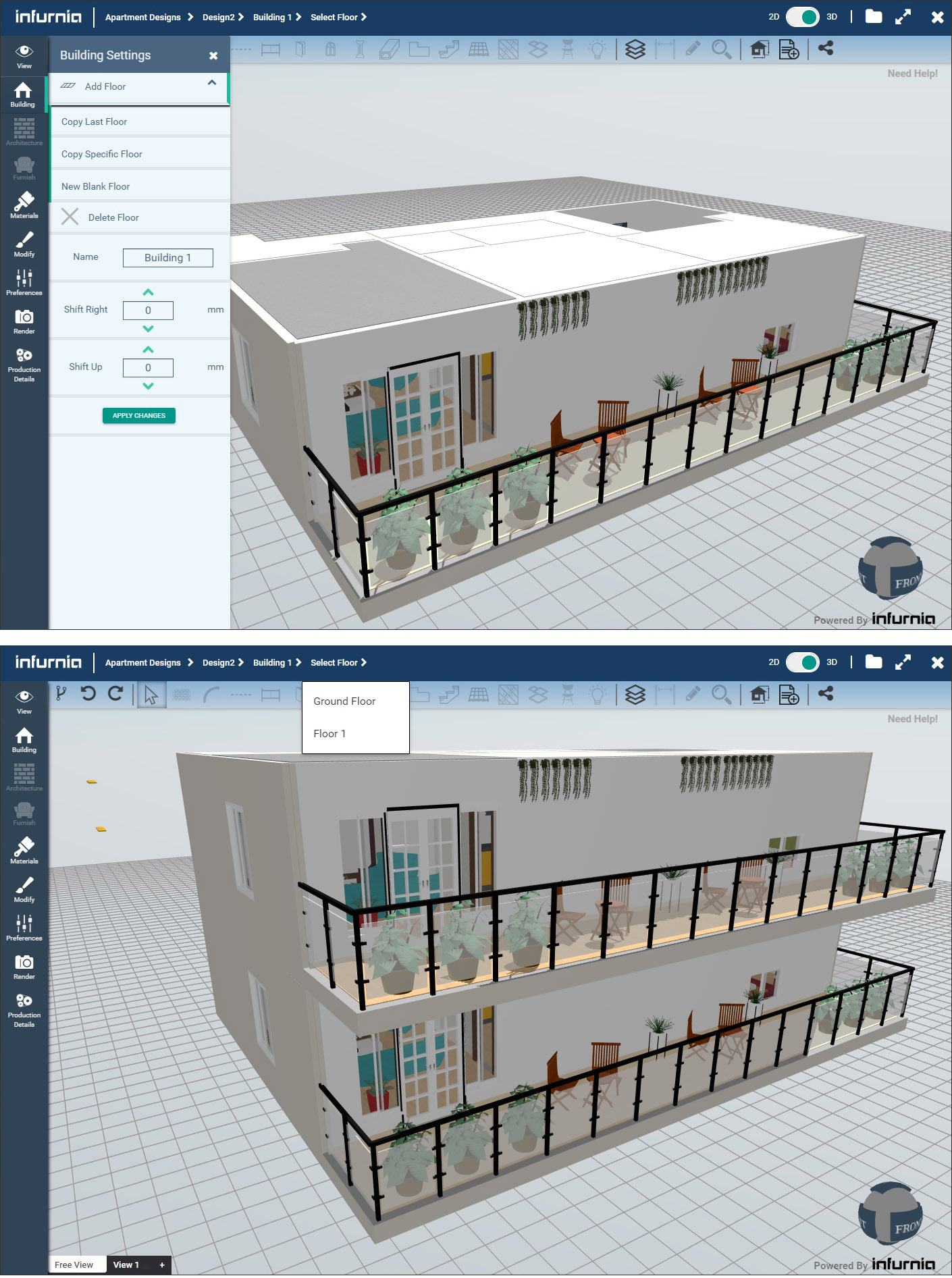
Additional floors to the design can be added by going to the Building level using the navigation bar at the top and then opening the Building settings from the toolbar on the left (Figure 10). Here, there are options to add a floor, either a blank floor or by copying any of the existing floors. This makes it easy to create, for example, a multi-story apartment block which has repeating floor plans. Once the new floor has been created, you can use the navigation bar at the top to select and activate it.
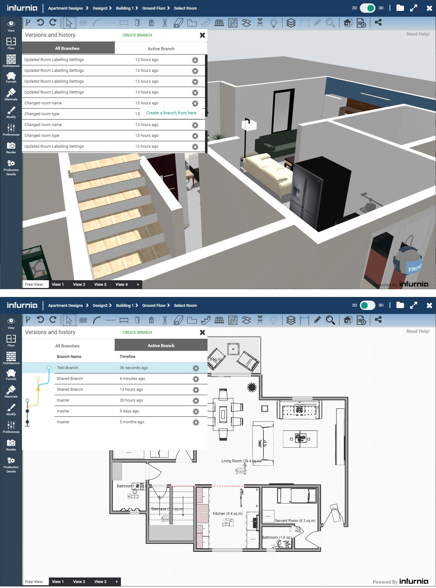
Infurnia allows multiple designers to be working on the same design simultaneously in a workflow that is similar to Google Docs. In addition, it has the concept of branches, which are essentially a means to allow designers to work on different parts of a design independently. A branch is created by accessing the version history of the project, which is a list of all the steps taken in the project so far. Any one of these steps can be selected and a new branch created from it, as shown in Figure 11. If you now look at a map of all the branches in the version history, you can see that the newly created branch is now the active one for you. Other team members could be working on different branches. Any branch can be merged back to the main branch when required.
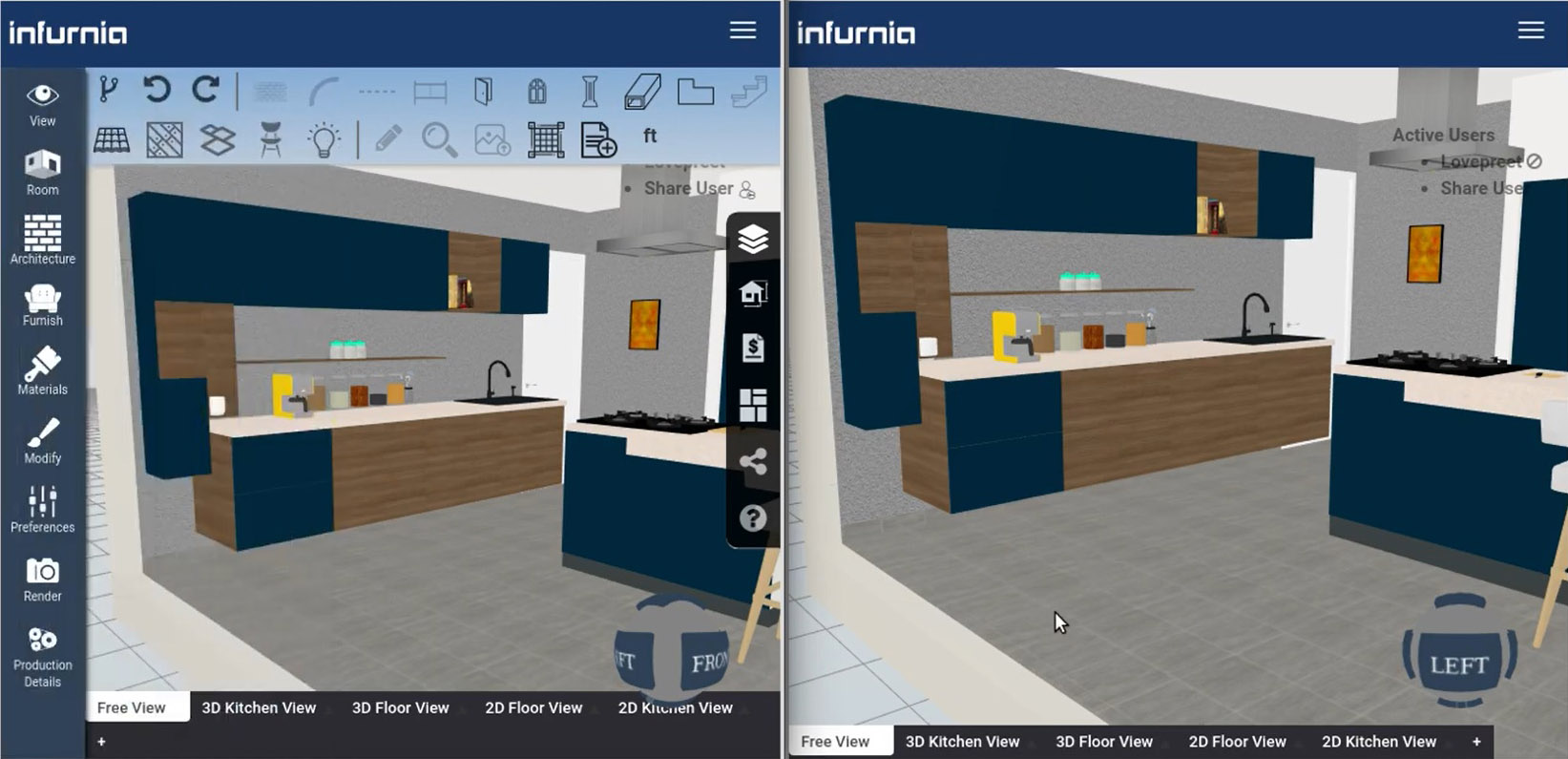
A design can be shared at any time with a customer through a URL that is generated by clicking on the Share Design button. They can click on the link to open up Infurnia on their browsers and explore the design; there are no editing tools in their version, so they cannot make any changes. An indication that another user is logged into the design is displayed in the designer’s interface. There is also the option for either of them to “follow” the other user, which allows the customer to follow the designer as he or she is making changes to the design in real-time (Figure 12), as well as allow the designer to follow the customer as they are navigating the design and discussing it.
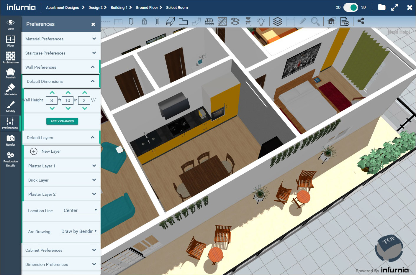
Some other capabilities in Infurnia that are noteworthy include the ability to set preferences for some of the default settings of different tools, such as the default height and construction layers for walls (Figure 13), the dimensions of the different components of a staircase, the external finishes of wall units and cabinets, the choice between the imperial and the metric system for dimensions, and many others. There is a full-fledged tiling module that allows detailed tiling patterns for floors and ceilings to be created, and even options for designing wall skirting, kitchen backsplashes, false ceilings, etc.
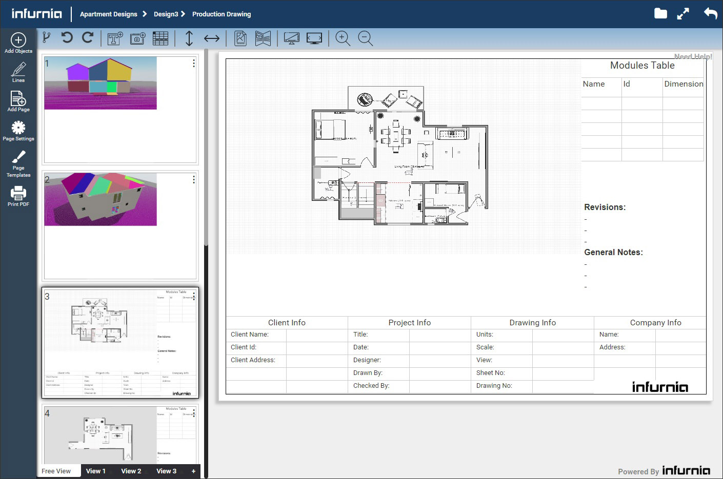
An important component of the design process is the creation of production drawings, and Infurnia supports this by allowing any of the views to be placed into drawing sheets, as shown in Figure 14. You can create templates to use for producing drawing sheets; add text, images, lines, and tables to individual drawing sheets; and specify page size and margins. The views that are placed in the drawing sheets are dynamic and always represent the current state of the design; any change made to the design is automatically updated in the drawings. There is the option to export a sheet as a PDF or export all the sheets as a PDF booklet.
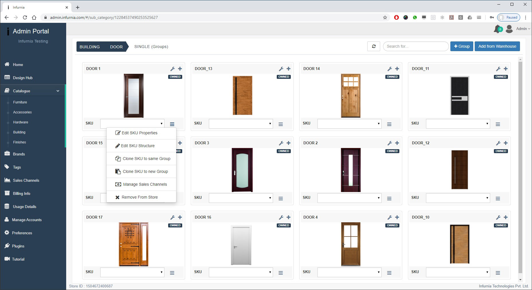
Infurnia has a separate Admin module for all administrative tasks such as account management, setting up user roles, creating custom catalogs of objects and materials, and monitoring the progress of projects in a firm. The most well-developed of these is the Catalog module, which allows objects such as doors, windows, columns, furniture, hardware, finishes, and so on to be added from a central warehouse that houses objects from different product companies (Figure 15). Once these are added by the Admin, they are available for all the designers of that firm to use in their projects. In addition to adding objects, their default dimensions can also be modified here.
I was very impressed by how much you can do in Infurnia, given that it is an entirely browser-based application. I was not aware that this level of functionality and content creation was even possible in a browser—needless to say, web technologies have certainly evolved, and being a new application, Infurnia has been able to use the most advanced technologies that are currently available.
It does not, of course, have all the bells and whistles of a full-fledged desktop design application, but for residential design, it is certainly a compelling option. The granular level of control for interior design concepts that can be achieved with it is amazing, and I found its “branching” and “follow” concepts especially innovative. Its overall interface is also very elegant and easy to use.
It was very refreshing to come across a startup application in AEC technology that showcases an entirely new way of doing things.
Lachmi Khemlani is founder and editor of AECbytes. She has a Ph.D. in Architecture from UC Berkeley, specializing in intelligent building modeling, and consults and writes on AEC technology. She can be reached at lachmi@aecbytes.com.
Have comments or feedback on this article? Visit its AECbytes blog posting to share them with other readers or see what others have to say.
AECbytes content should not be reproduced on any other website, blog, print publication, or newsletter without permission.