


FINE MEP is a complete set of BIM applications for MEP design. It is part of 4M’s multi-disciplinary BIM suite, which also includes IDEA for architectural design and FineGREEN for sustainable design and analysis. The objective of 4M, which was started in 1986 and is headquartered in Greece, continues to be to provide the design and engineering community with powerful yet low-cost applications, as with IDEA for architectural design, which I reviewed last year.
4M’s applications were initially built on top of the open-source IntelliCAD format, the low-cost alternative to AutoCAD that is compatible with the DWG file format. 4M is now also using the ODA (Open Design Alliance) Drawing Toolkit, and this, along with a 64bit architecture, has made its applications faster and more powerful. Even with these changes, their cost remains a fraction of BIM applications such as Autodesk Revit and Bentley OpenDesigner, making 4M’s applications extremely popular in many countries all over the world where cost is a key deciding factor.
FINE MEP is a suite of applications for six verticals in the field of MEP engineering. These include:
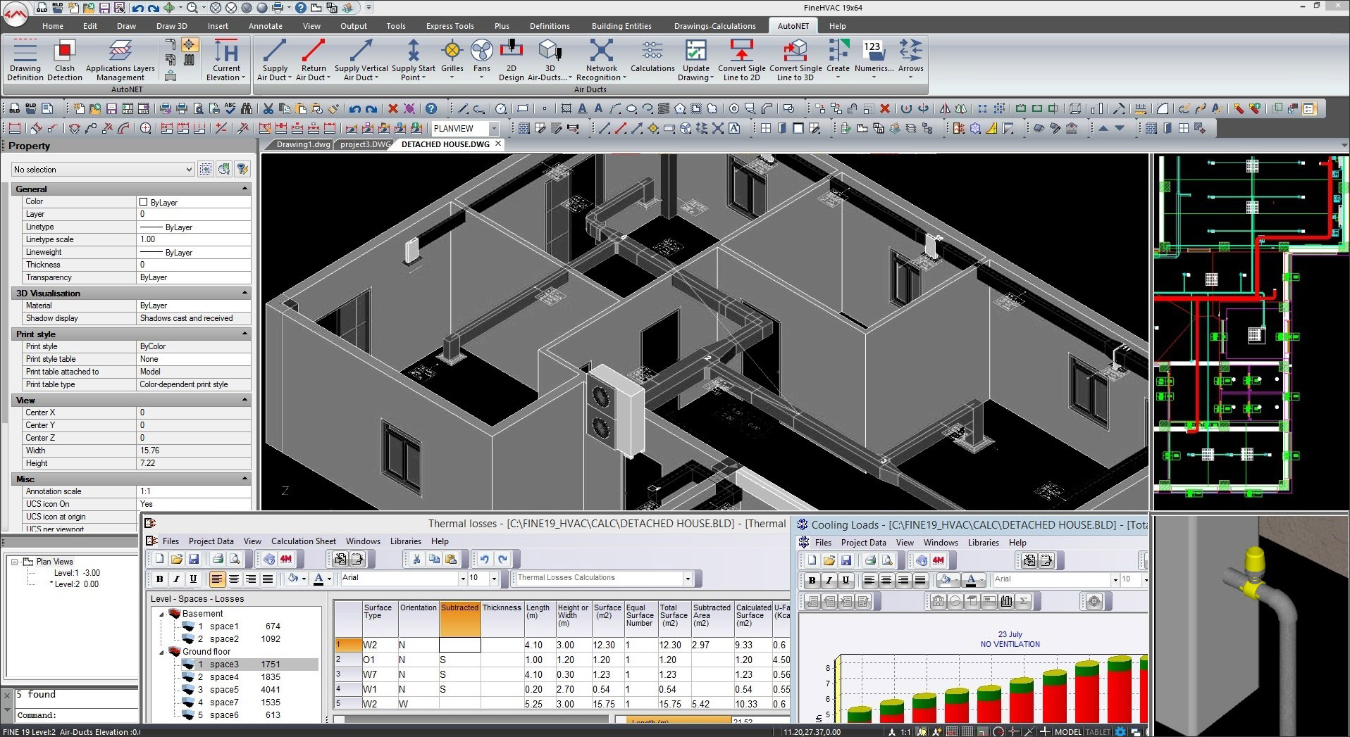
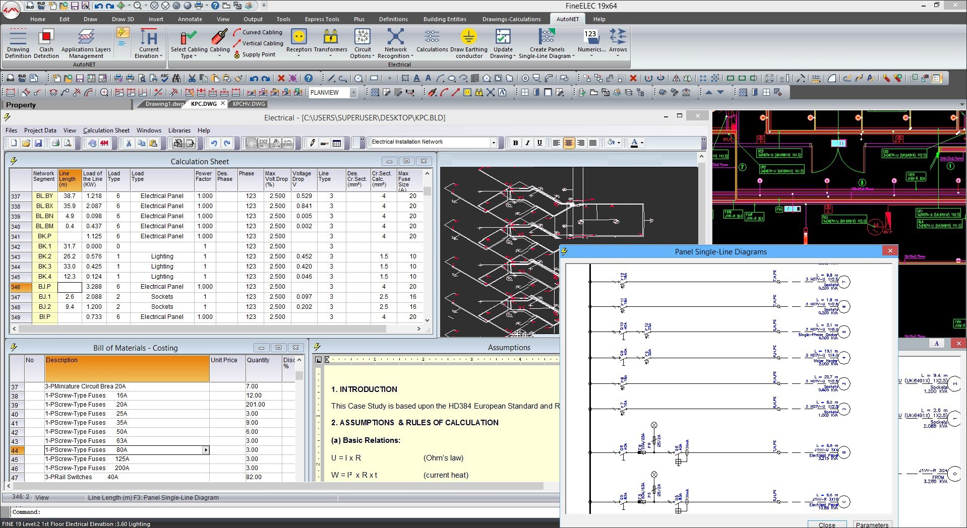
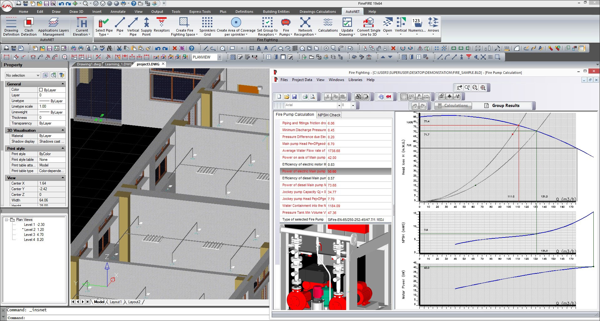
Each individual application includes all the discipline-specific functionality that would be required for an engineer in that domain to create and document a design. So, for instance, FineHVAC includes tools for designing heating and cooling networks, air ducts, supply lines, grilles, fans, floor heating systems, etc. It performs all the required calculations for any HVAC installation and generates the calculation sheets, technical reports, bill of materials and costing, as well as the final drawings including plan views, 2D/3D isometric piping/ducting drawings, 3D perspective views, and details (Figure 1). FineELEC, the application for electrical engineering, has tools for designing cables, circuit boxes, wiring, receptors, transformers, etc., and can generate the needed panel diagrams based on the design in addition to calculations, bill of materials, and other deliverables (Figure 2). Similarly, FineFIRE allows a Fire Safety engineer to design the network of water pipes, sprinklers, hoses, pumps, and sensors that would be needed to activate the sprinklers in a building in the event of a fire (Figure 3).
For engineering firms that do not need all of these applications, they are also available for purchase individually as an alternative to buying the entire FINE MEP suite.
As evident from the interface images shown in Figures 1, 2, and 3, a key feature of all the FINE MEP applications is the familiar AutoCAD-like interface, complete with the command line, which makes them much easier to learn and use for the vast majority of MEP professionals who have been primarily using AutoCAD so far. It makes the transition to BIM much easier for them. The native file format of FINE MEP is DWG, so any AutoCAD and AutoCAD-compatible files can be opened directly in any FINE MEP application and vice versa.
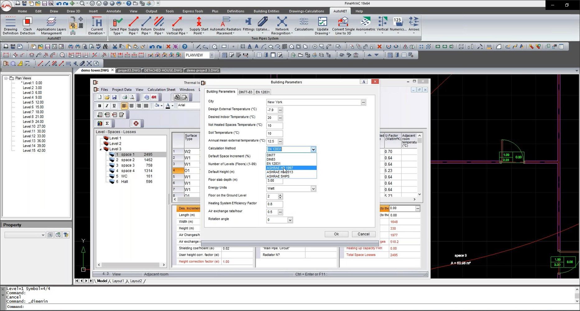
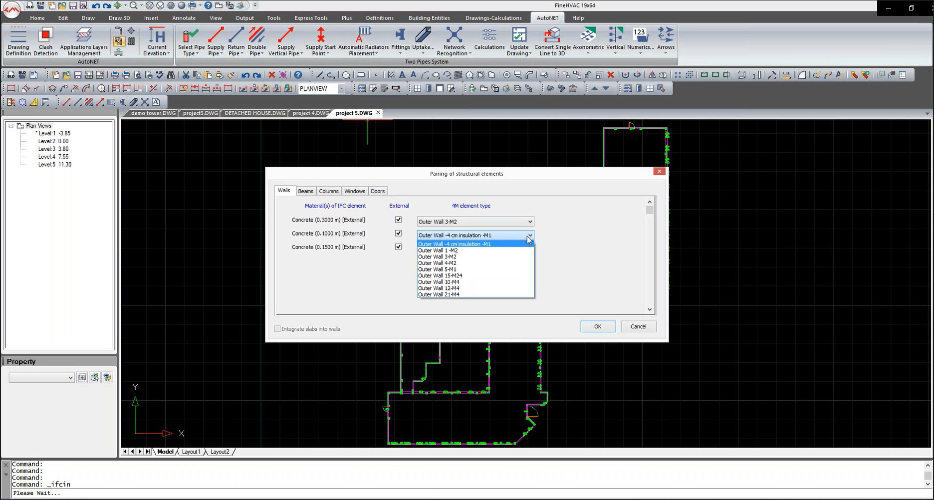
Another key distinguishing feature that sets FINE MEP apart is the support for multiple MEP norms and standards such as EN, DIN, BS, ASHRAE, NFPA, etc., that are prevalent in different countries. (The complete list is shown in Figure 4.) The calculations that drive the design of an MEP system, as well as the type of annotations, depend upon the standard that has been selected (the choice of which is made as shown in Figure 5.) This support of multiple standards in FINE MEP is in contrast to an application like Revit MEP, which is somewhat of a generic MEP application whose ability to design for a particular standard comes from a third-party add-on that has to be purchased separately.

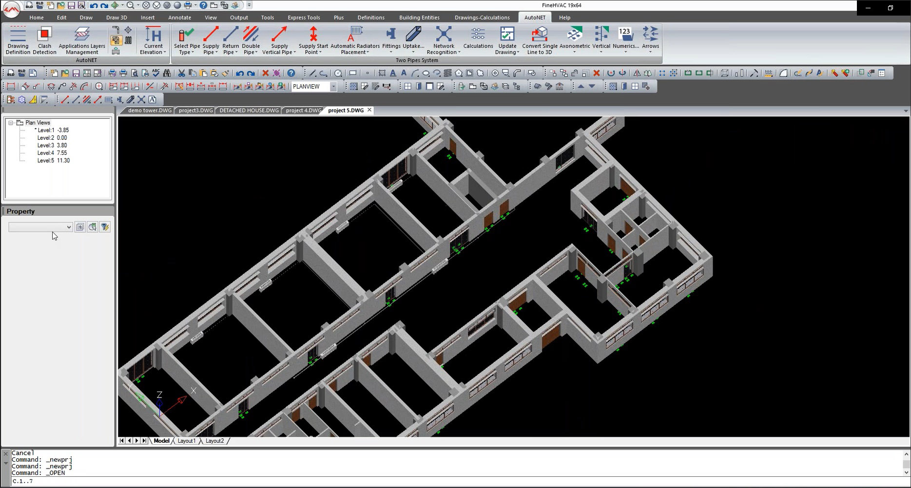
The typical starting point for an MEP engineer is the design of the building that has been created by the architect in conjunction with the structural engineer. This design is made available to the engineer either in the form of a BIM model or the individual drawings of each of the floors. If the design is in the form of a BIM model, it can be brought into any of the FINE MEP applications in the form of an IFC file. You would typically do some mappings of the imported IFC elements with the corresponding elements in FINE MEP (Figure 6), after which you would have the building description in FINE MEP. The levels of the building are automatically created, as shown in Figure 6, where the IFC building that is being imported has five levels. The 3D view of Level 1 of the imported IFC model is shown in Figure 7.
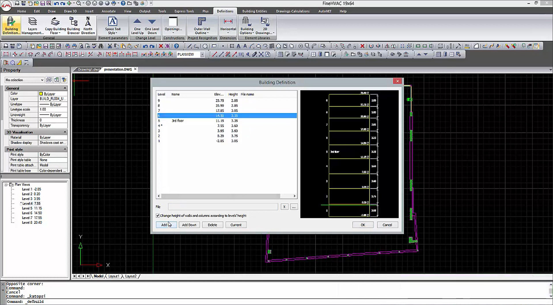
If the building design is only available in the form of plan drawings, you can create a building structure in FINE MEP (as shown in Figure 8), import the building plan for each floor as a reference, and create the walls, doors, windows, beams, columns, slabs, etc., using the corresponding FINE MEP tools to define the 3D building model. It is easier if the drawing is in the form of a DXF or DWG file as you can snap to its points; als0, entities like walls edges are automatically detected. But you can also bring in PDFs and image files. This way of defining the building is especially helpful for the large number of projects in smaller firms over the world that are not yet using BIM.
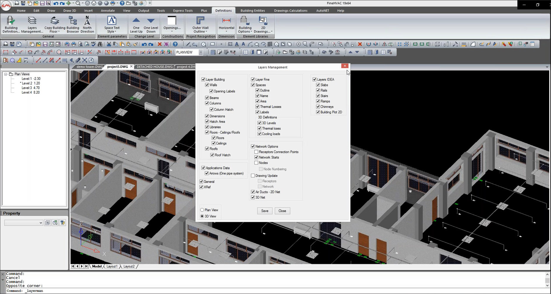
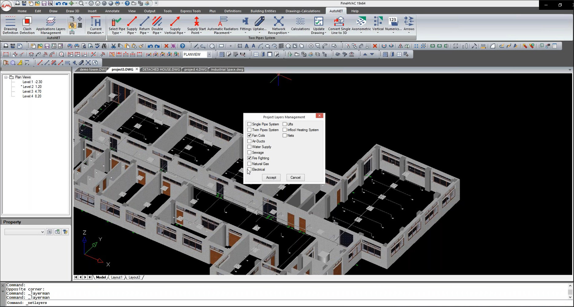
Of course, if the building design has been created in IDEA Architecture, it can simply be opened in FINE MEP and is immediately available to the MEP engineer. A Layers Management dialog provides the option to turn off the display of IDEA entities when required (Figure 9). There is also a separate Applications Layer Management dialog that lets the MEP engineer control the display of the designs created by the individual FINE MEP applications such as HVAC, electrical, fire-fighting, gas, etc. (Figure 10)
One of the main advantages of using the applications in the FINE MEP suite for MEP engineering is the use of automatic calculations, based on rules and the selected standards, to automatically design details of the system such as element sizes and placement so that the engineer can focus on the bigger picture and higher-level design. Wherever there are standard rules for placement—for example, heating/cooling units under windows, air-grills at the space center for small spaces or on grids for larger spaces, and so on—they are being applied. Routing routines for pipes and cables are semi-automated, with the user indicating starting and ending points, running parallel to walls, etc. The sizing of elements is fully automated following the standard that is to be adopted. Needless to say, any of these automatically derived attributes can be changed by the user at any time.
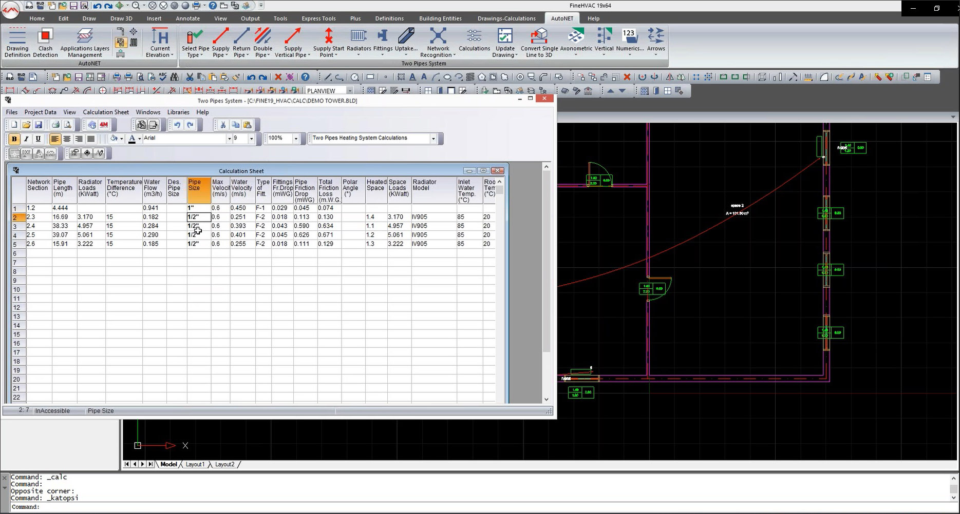
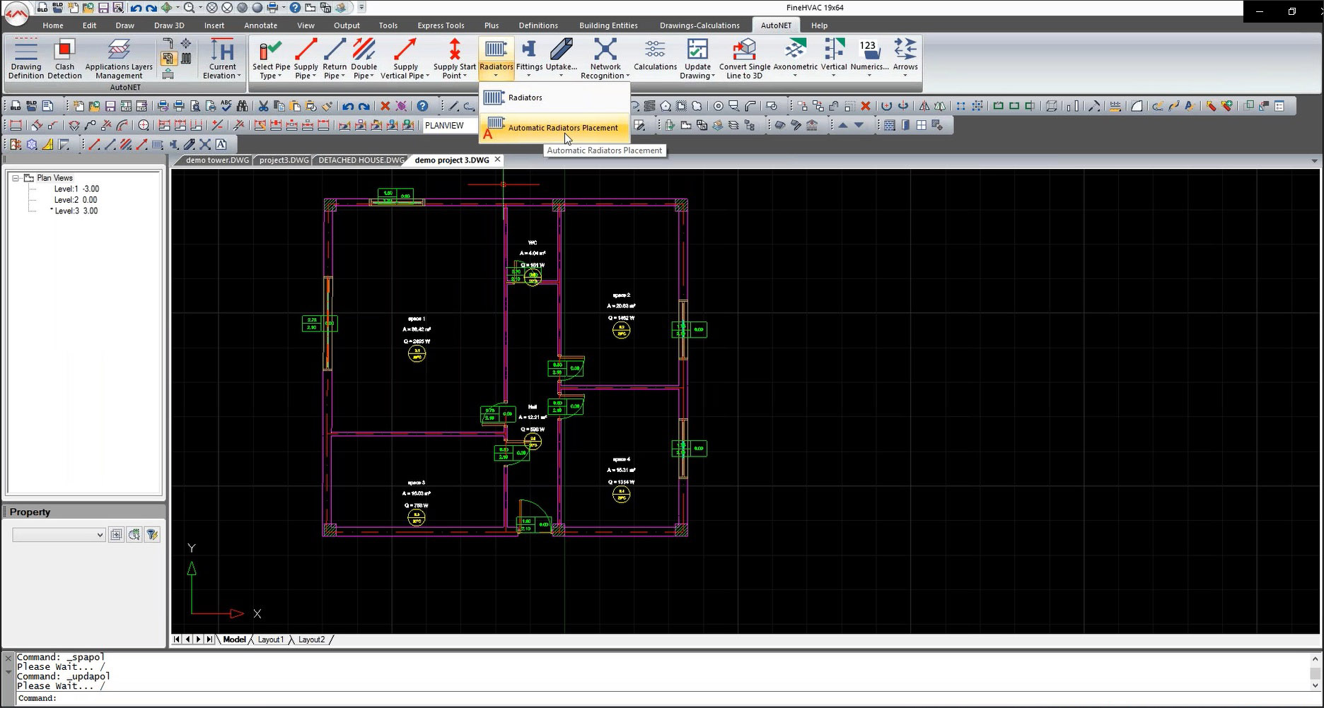
Some examples of these smarts from the different applications in the FINE MEP suite are illustrated here. Figure 11 shows the calculation worksheet for an HVAC installation, where the pipe sizes of the different network sections have been automatically calculated based on hydraulic constraints that should be satisfied such as the water velocity and/or friction, etc., as specified by the standard that is being used. Another example is the automatic placement and sizing of radiators in front of windows, selected as shown in Figure 12.
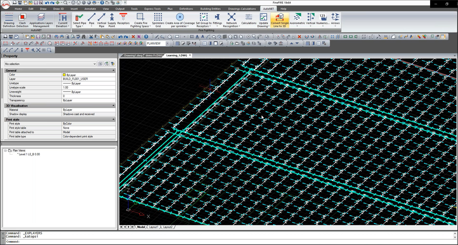
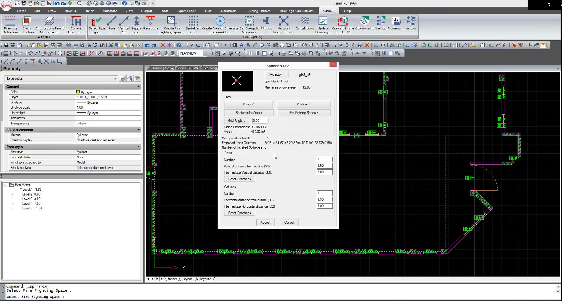
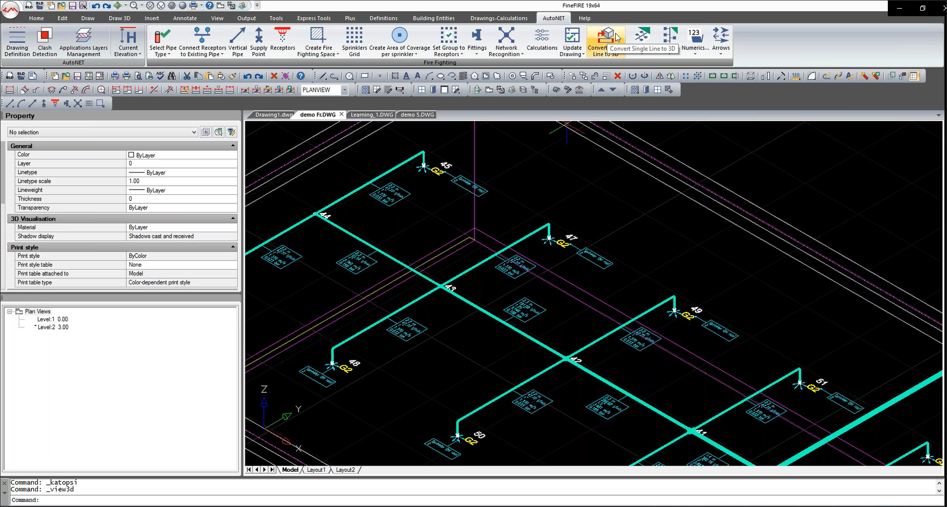
In the example shown in Figure 13, a network of 3000 nodes of sprinklers in FineFIRE was automatically generated by specifying some key parameters such as the location of the main pipes and the size of the grid. Figure 14 shows some of the smarts of the application, where the minimum number of sprinklers in a grid is suggested based on the area to be covered, the density of water (which comes from the standard) and the type of hazard (OH stands for “ordinary hazard”). The settings for the grid can be fine-tuned here, after which all the sprinklers are placed automatically. When converted to 3D, the sizes of the individual pipes come automatically from the calculations (Figure 15).
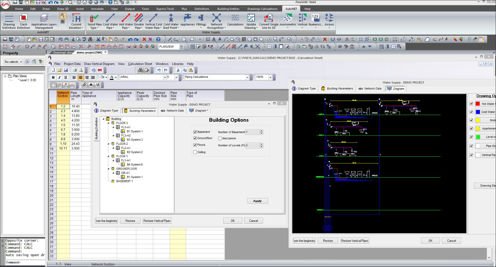
In addition to the automatic calculations and details, there are also some “smart wizard tools” in some of the FINE MEP applications which can generate an entire network, such as in FineSANI by specifying some basic options for the entire building (Figure 16).
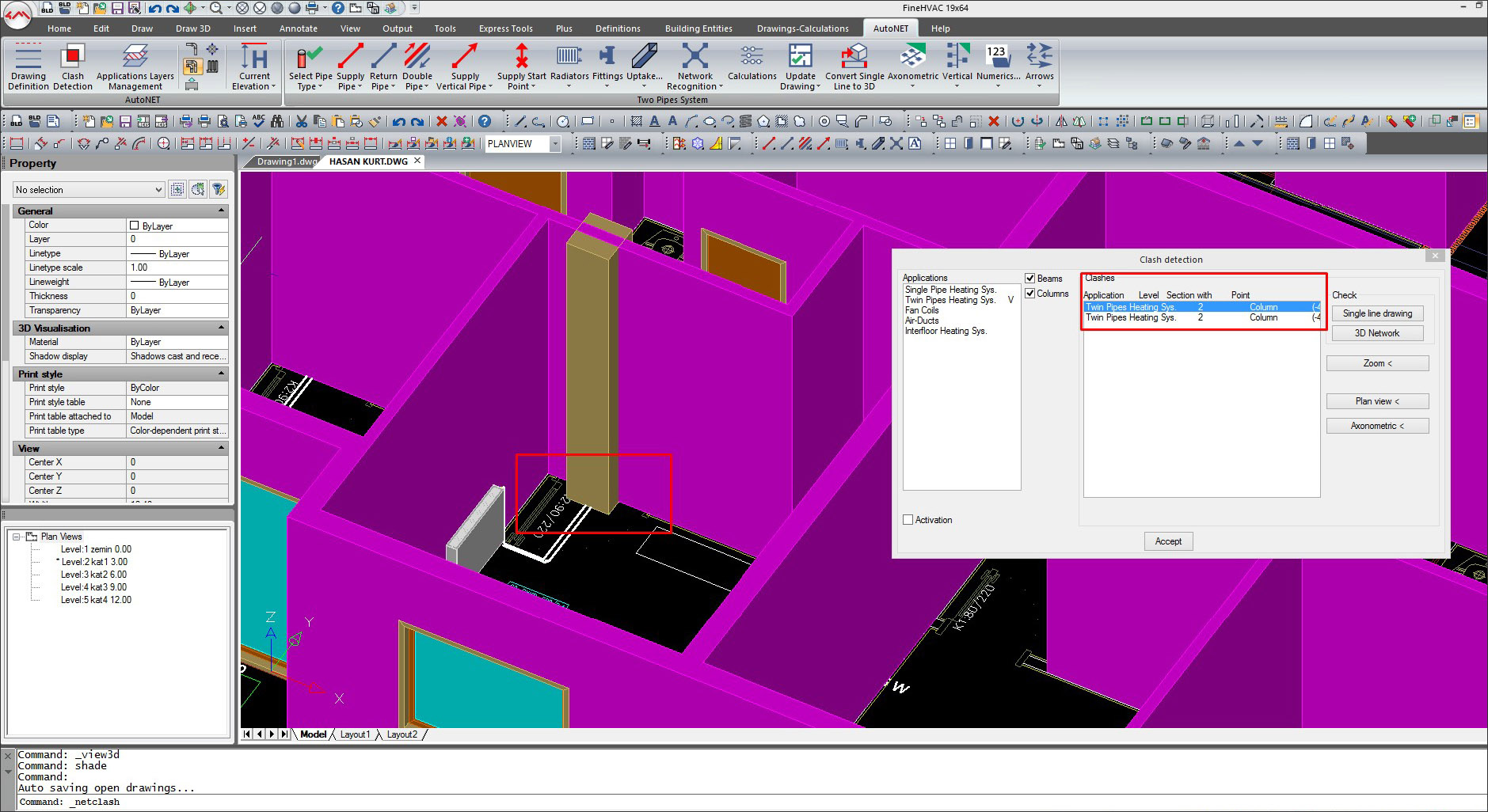
And finally, a key capability of FINE MEP is the ability to perform clash detection to ensure that the design of HVAC/Plumbing/Electrical networks is free from clashes with each other and with the structural design. (Figure 17).
4M’s FINE MEP suite of applications may not have all the bells and whistles of the top-of-the-line BIM applications such as Revit MEP, but what they lack in sophistication, they make up in cost efficiency, a familiar AutoCAD-like interface, DWG functionality, and compliance with all the leading international standards, allowing them to be used in countries around the world. They have a broad range of capabilities and are still relatively lightweight, with files sizes that are smaller and easier to work with.
So much of MEP engineering is driven by calculations, and the use of a BIM suite like FINE MEP that automates much of the grunt work gives engineers more time and energy to focus on the higher-level aspects of the design. These engineers now have a simple and cost-effective way to transition from CAD to BIM. The ability to import IFC files allows MEP engineers to be part of a collaborative BIM workflow with architects and structural engineers, and 4M is working on the ability to import Revit files, which will allow MEP engineers working with FINE MEP to work directly with architectural and structural designs modeled in Revit.
All in all, MEP engineers can now get up to speed on BIM quickly, on their own as well as part of a multi-disciplinary project team.
Lachmi Khemlani is founder and editor of AECbytes. She has a Ph.D. in Architecture from UC Berkeley, specializing in intelligent building modeling, and consults and writes on AEC technology.
Have comments or feedback on this article? Visit its AECbytes blog posting to share them with other readers or see what others have to say.
AECbytes content should not be reproduced on any other website, blog, print publication, or newsletter without permission.