


The Nemetschek brand, Solibri, developer of the leading and longest-standing model-checking application in the AEC industry, Solibri Model Checker (which was renamed “Solibri Office” in 2019), started the new year by expanding its product family with a new cloud-based model checking solution called Solibri CheckPoint. This new solution is based on Solibri’s acquisition of Xinaps and its Verifi3D product, and it enables model-checking of Revit and IFC models to be done much more easily and quickly using just a web browser. Additionally, Solibri CheckPoint integrates with platforms like Autodesk Construction Cloud (ACC), BIM 360, and Procore, allowing the project models hosted there to be pulled in automatically, checked, and reported on.
I had briefly looked at Verifi3D in 2019 a month before it was launched by Xinaps: see the article “AEC Technology Updates, 2019.” Let’s look at its new avatar in the form of Solibri CheckPoint.
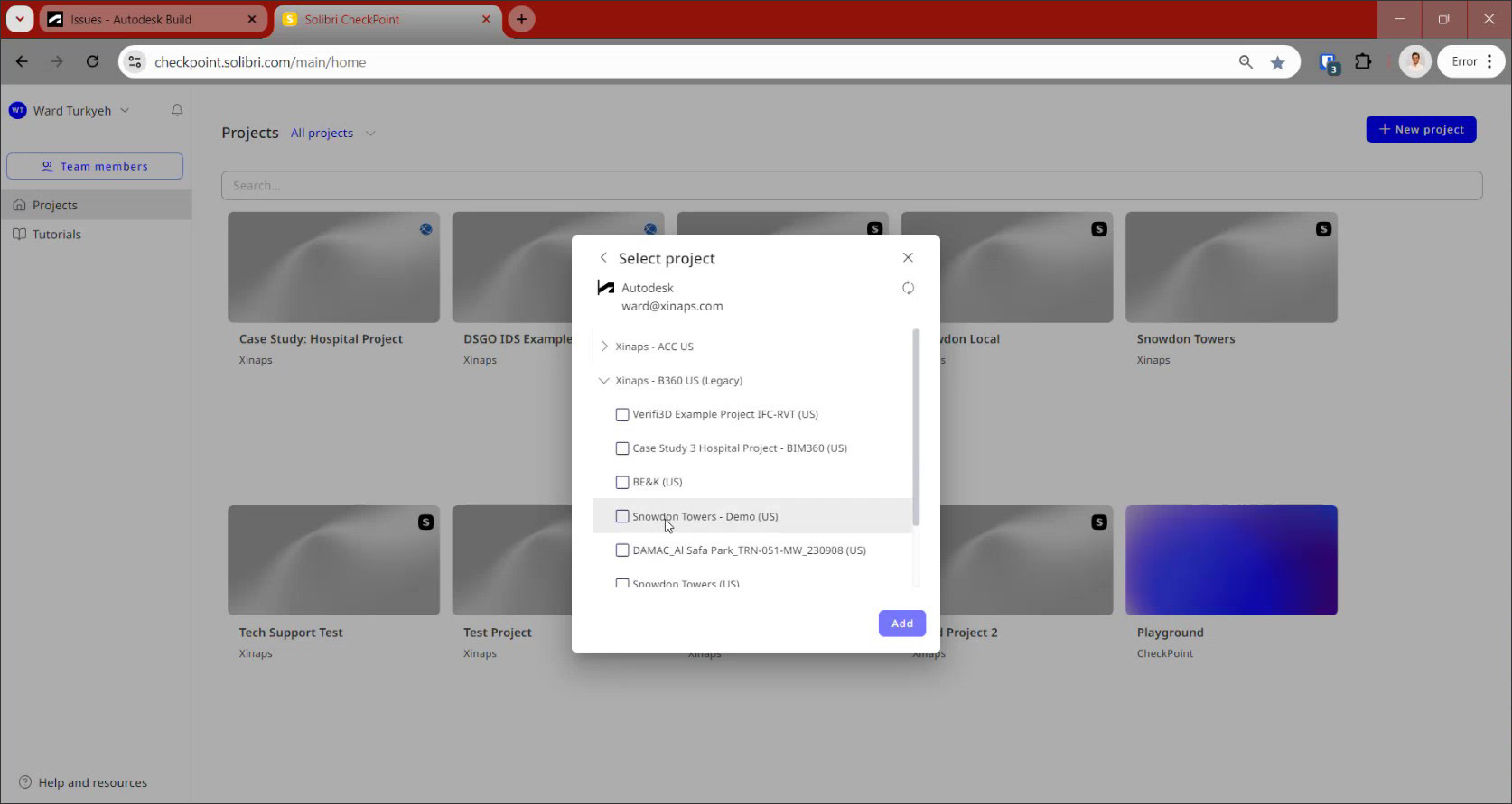
There are two ways to import models for checking into CheckPoint. You can create a new project and upload the models to it, or you can connect to your Autodesk or Procore account and select a project from there to import into CheckPoint (Figure 2). The projects that are imported are indicated by the ACC, BIM360, or Procore logos, indicated that they are directly connected to those CDEs. And as with those project hubs, CheckPoint is also a collaborative platform, allowing multiple team members to work on the model checking.
Clicking on any project takes you directly to the 3D viewer of CheckPoint, shown in Figure 3. In the panel on the left are the main tools for importing the models, federating them into model sets, viewing element data, applying filters to select required subsets of elements, creating and applying validating rules, and generating issues to report the results of the model checking.
The models can be imported in Revit or IFC format and once they are in CheckPoint, you can combine them in different ways to create different model sets for checking. So, for example, in the project shown in Figure 3, six different models were imported of which three were combined in the IFC-Revit Model Set that is shown: the architectural model in RVT format and the structural and MEP models in IFC format. The panel on the right shows more information about a selected file, while the combined model is displayed in the 3D viewer. The viewer includes all the standard navigation capabilities including isolating elements, sectioning the model, measuring distances, and grid display.
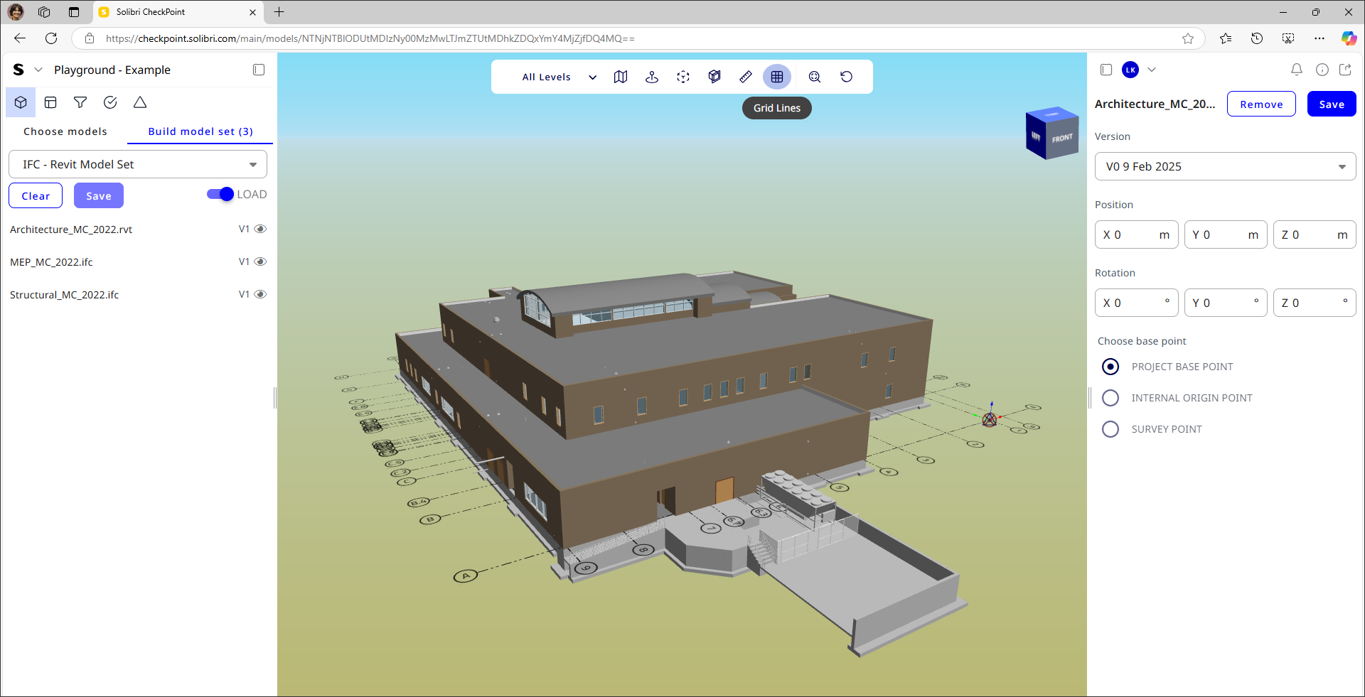
It should be noted that if the project had been imported from ACC or Procore, the connection with that CDE is maintained and any new versions of the models published in those hubs are automatically brought into CheckPoint, from where they can be pulled into model sets for checking. Also, if the different disciplinary models are not already aligned prior to import, their positions can be manually adjusted with the settings shown in the right-side panel in Figure 3.
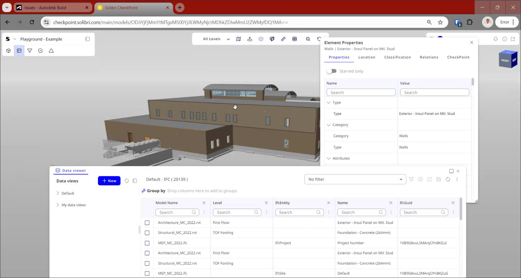
To explore the individual elements of the combined model in more detail, you can right-click on an element to view its properties. The information displayed here will depend upon whether the element is from a Revit file or an IFC file. CheckPoint supports all Revit properties, including type parameters and shared parameters. Another way to view the model is by selecting the Data Viewer tool, which allows you to show a group of selected properties for the elements in the 3D viewer, such as the level, element type, classification, area, volume, etc. Both these interface elements are shown in Figure 4. The Data Viewer tool allows the selected elements to be exported to CSV or Excel, enabling CheckPoint to also be used for QTO (quantity takeoff).
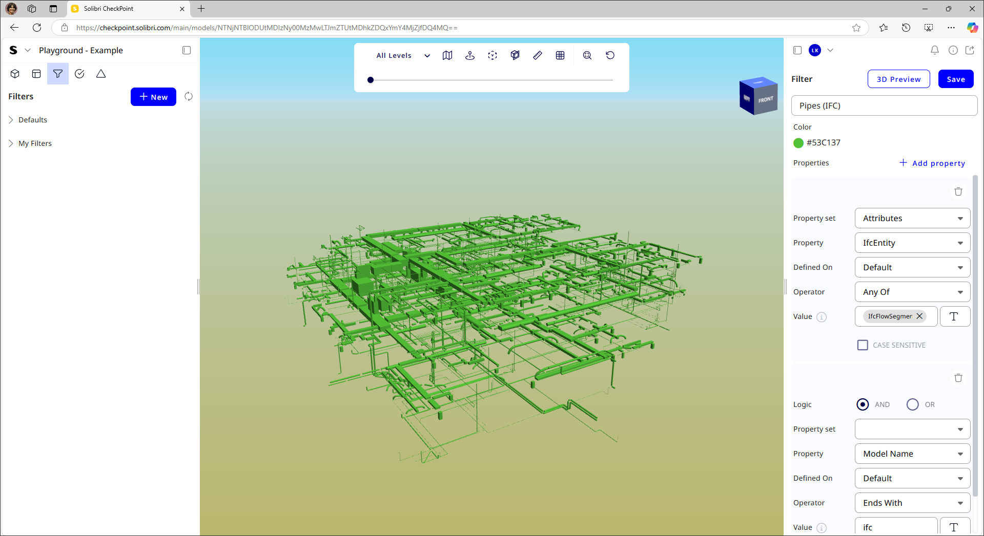
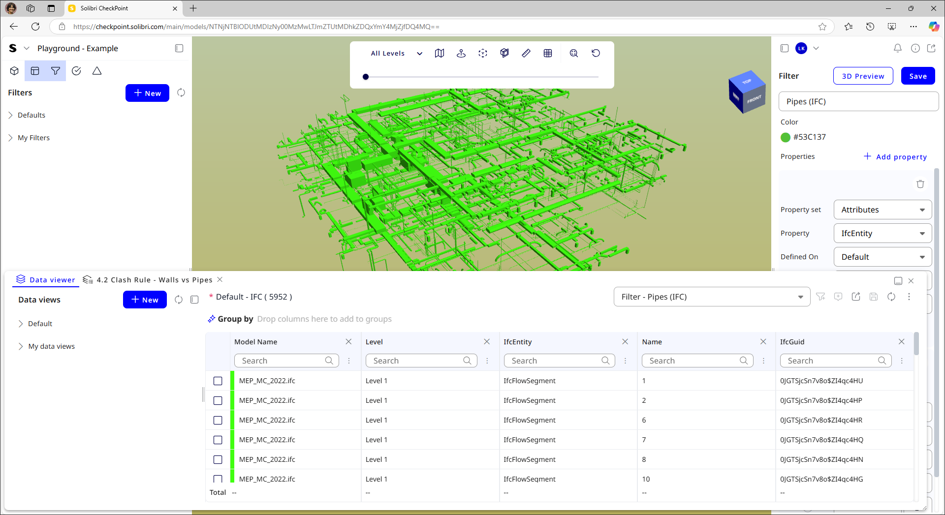
In order to be able to apply any kind of checks to the model, you first need to be able to select different categories of model elements, and this is done by using filters. An example is shown in Figure 5, where a filter is applied to select all the pipes in the model that are in the IFC format. The selection can be narrowed down further by progressively applying additional filters using And/Or logic, as shown. Multiple filters can be created in this manner and saved for easy access for use in model checking. Opening up the Data Viewer interface when a filter is applied shows the list of the displayed elements in tabular format along with their total count, which is 5,592 in the example in Figure 5.
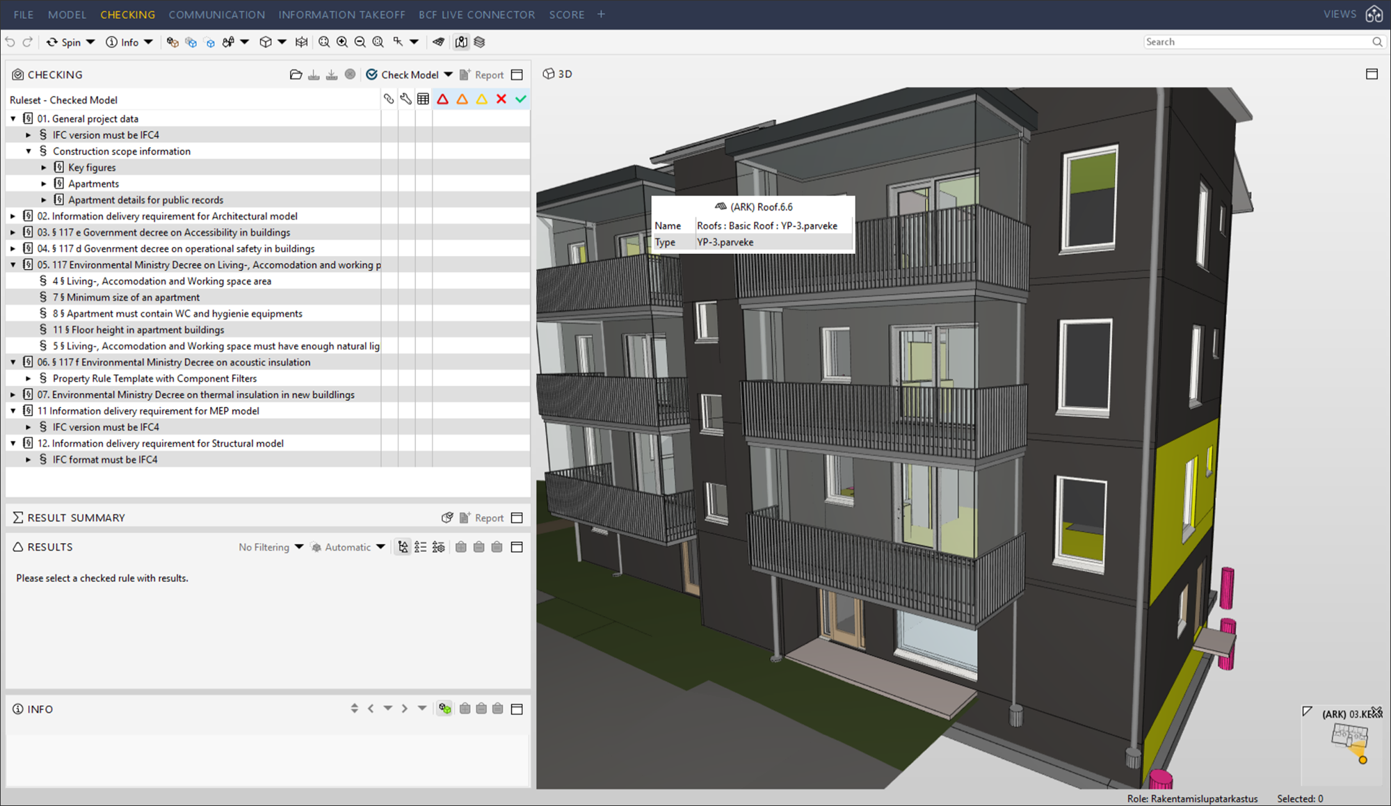
For checking the model, you need to create rules, and as of now, Solibri CheckPoint has three main kinds of rules that can be applied to the model: Clash Check, which identifies conflicts between building elements, such as mechanical and structural components; Property Check, which checks model elements to ensure they have the required properties for meeting accuracy, consistency, and compliance standards; and Free Space Check, which can check for adequate clearance around critical elements to ensure functionality and safety, such as door swings, accessibility for mechanical and electrical equipment, and so on.
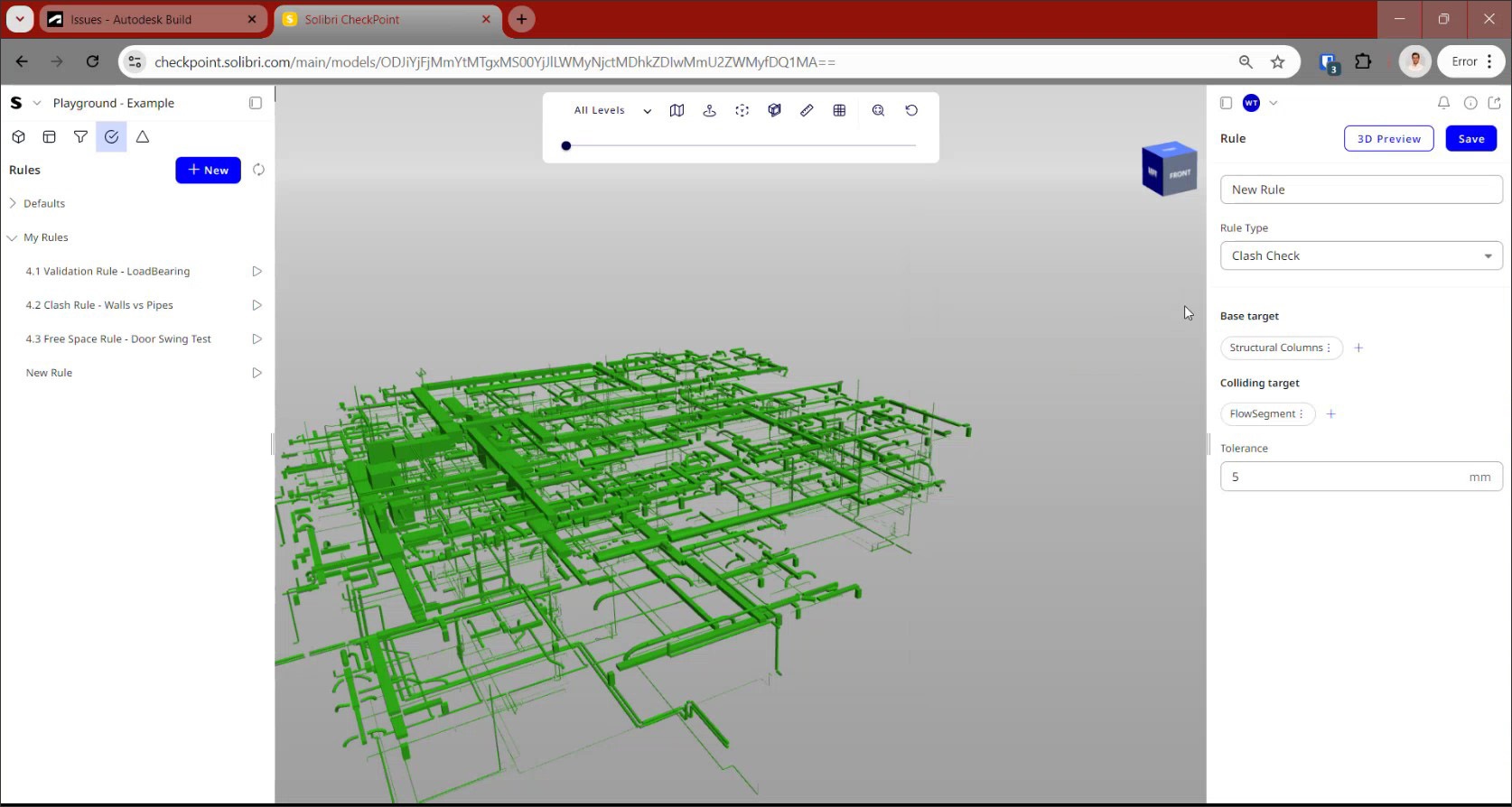
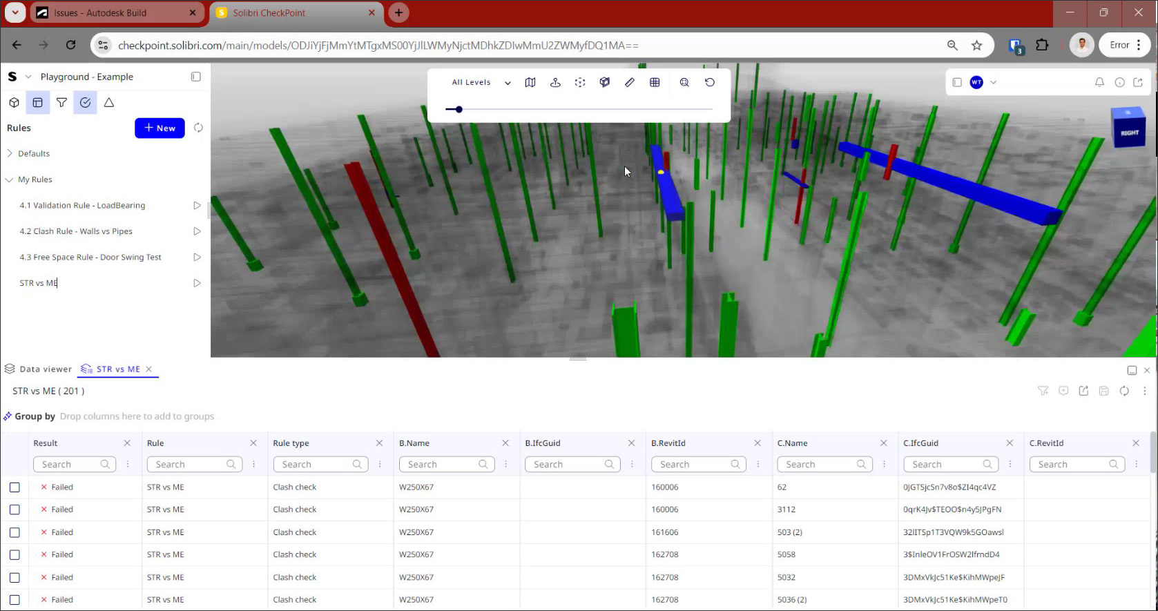
For performing a Clash Check as shown in Figure 6, you would select a set of elements as the Base target and another set of elements as the Colliding target. Both of these groups of elements can come from filters that you have previously defined, or you can create a filter set on the fly using the options that were shown in Figure 5. You can also specify the tolerance value that should be used for the collision detection. You can now run this Rule and any clashes that are detected will be shown in the 3D window, with more detailed information about each clash available in the Data Viewer that opens up automatically.
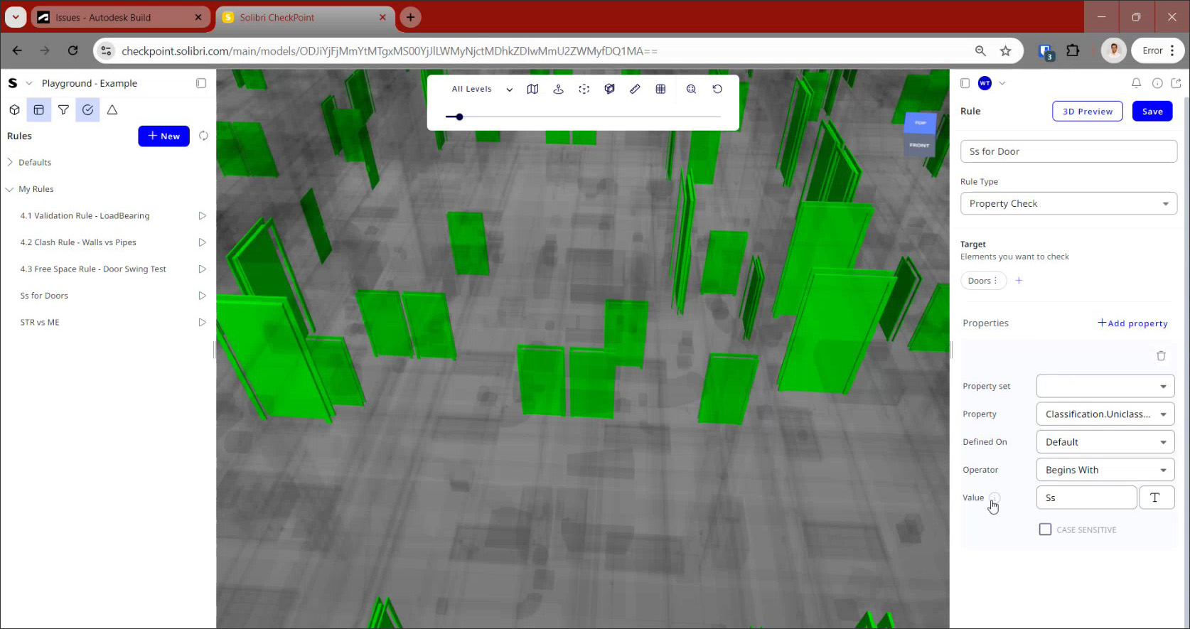
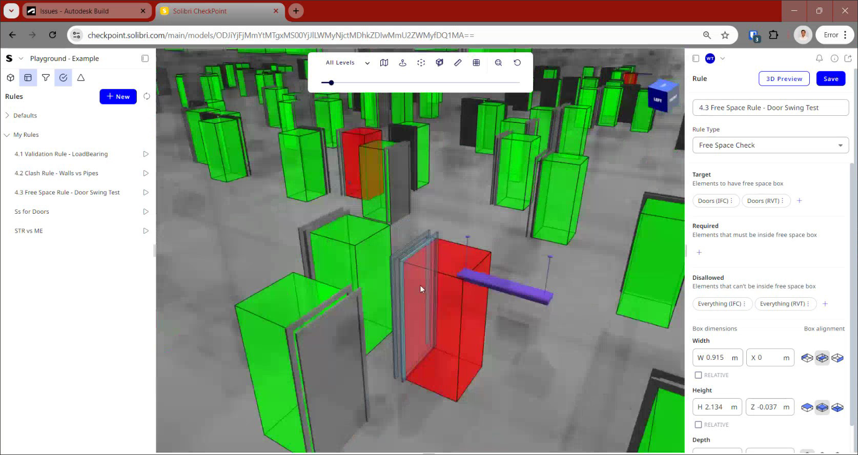
An example of a Property Check is shown in Figure 7, where all the doors in the model are being checked to ensure that they meet a specified naming convention: that all the values for the “Classification.Uniclass.Ss.Number” property start with the letters “Ss.” Solibri CheckPoint also offer the ability to use wildcards for the Value field to expand the checking capability. The third type of rule, Free Space Check, is illustrated in Figure 8, where the doors in the model are being checked to ensure that they have enough room to accommodate their respective door swings. This is done by specifying the dimensions of a bounding box around the element as well as additional settings including required and disallowed elements within that box.
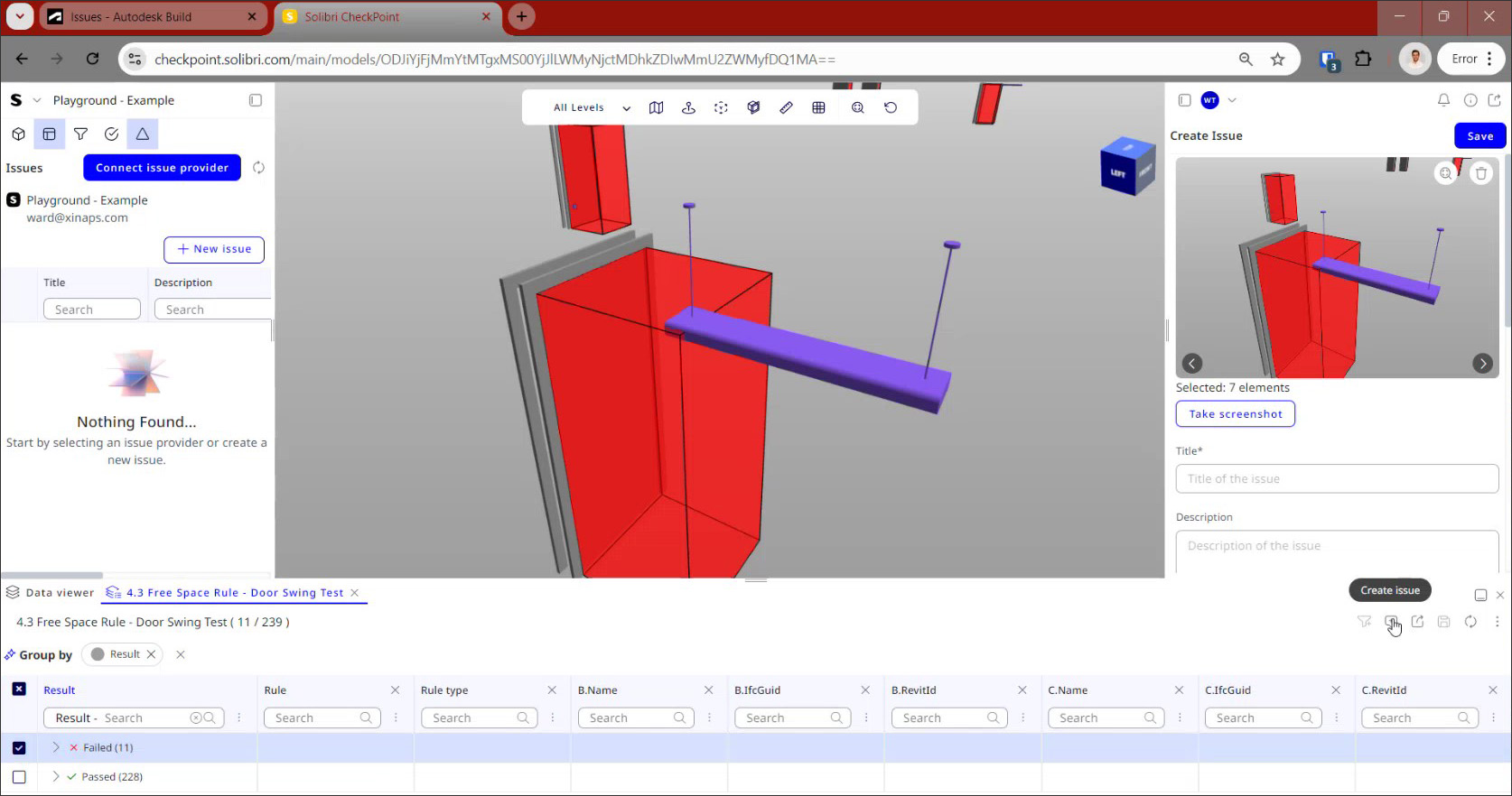
The final step in Solibri CheckPoint is to create issues from the problems that were detected and share them with the design team so that the problems can be fixed in the authoring applications. This is easily done by selecting any of the checking results in the Data Viewer and using the “Create Issue” tool, as shown in Figure 9. You can take a screenshot of the issue from any angle, add information about the issue such as title, description, priority, due date, etc., and save it internally in CheckPoint. All of the issues that are created can be exported in the standard BCF format that is used for collaboration and issue management.
In addition to exporting to the BCF format, Solibri CheckPoint can also connect directly to an external issue provider. The list currently includes ACC, Procore, and BIM360, which are also the CDEs that CheckPoint integrates with. This means that not only are the project models created in these hubs automatically brought into CheckPoint, but also that the issues created in CheckPoint are automatically reported back to those CDEs from where they can be managed without needing to be specifically saved or exported to them.
With the growing move towards cloud-based applications in every industry, Solibri CheckPoint is an important addition to the Solibri product family, which has, until now, been defined primarily by its flagship desktop-based Solibri Model Checker (SMC) application.
While SMC is a very powerful, comprehensive, and sophisticated application for a wide range of model checking capabilities – and the foundational application for any kind of automated code-checking initiative (see the articles, “Automated Code Compliance Updates, 2018” and “CORENET e-PlanCheck: Singapore's Automated Code Checking System”) or BIM-based permitting of the kind shown earlier in Figure 1 – what Solibri CheckPoint brings to the table is a much easier and accessible way to check individual models as well as federated multi-disciplinary models to make sure they are accurate, compliant, and clash-free. In addition, its support for native Revit files and the seamless integration with project hubs like Autodesk Construction Cloud, BIM 360, and Procore — which automatically brings in model revisions and sends back the issues discovered during model-checking — is a huge plus.
It has made the barrier to entry for model-checking in the AEC industry so low that there seems to be little reason not to make model-checking a commonplace step in the AEC workflow.
Lachmi Khemlani is founder and editor of AECbytes. She has a Ph.D. in Architecture from UC Berkeley, specializing in intelligent building modeling, and consults and writes on AEC technology.
Have comments or feedback on this article? Visit its AECbytes blog posting to share them with other readers or see what others have to say.
AECbytes content should not be reproduced on any other website, blog, print publication, or newsletter without permission.