


Similar to tools such as Ideate BIMLink and CTC BIM Project Suite, Revittools is a plugin for Autodesk Revit that provides another solution with comparable functionalities for managing BIM model data and exporting data to external databases like Excel. It is developed by Codemill, a software development company based in Finland that specializes in developing software products and services for AEC industry. They also create plugins for other applications including AutoCAD, AutoCAD Plant 3D, and Navisworks. We described their Navisworks plug-in, Navistools, in detail earlier this year. Here, we do the same with Revittools, providing an overview and describing how it works.
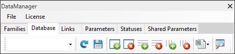
As shown in Figure 1, the plugin has six main functional tabs: Families, Database, Links, Parameters, Statuses, and Shared Parameters. The “Families” tab allows users to extract and tabulate model elements listing their Revit category, family, and type. The “Database” tab allows users to create a table for the elements listed in the “Families” tab and populate it with user-defined information. The information can be embedded in the model and attached to the elements as shared parameters using the “Shared Parameters” tab. The “Parameters” tab provides some of the properties related to each element in the model. The “Links” tab provides fields to attach web links and external files to the elements within the model. Finally, the “Statuses” tab allows the user to track the elements by assigning a color to them based on different user-defined conditions.
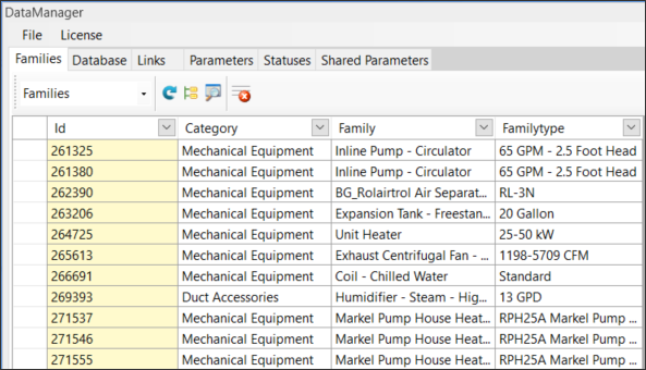
Users can extract existing model elements using their Revit IDs with their category/family/type information and populate a table by selecting the “Populate Families” tool as shown in Figure 2. Once a list with all the elements is created, users can review the elements by their category, family, or family type. If any element is added to the model, this list can be updated using the “Refresh” tool. To filter the data and narrow down the list to include the desired elements, the dropdown menu from the category, family, or family type columns can be used for filtering the results. Additionally, the user can remove a single row or a set of rows using the “Remove Rows” tool.
By clicking on any field in the table, the graphical representation of the corresponding element will be highlighted in the model view. An alternative would be to select an element in the model and use the “Find Selected Element” tool to find it within the table.
Using functionality under this tab, users can create multiple database tables and populate each table with new information for model elements listed under the “Families” tab. This is a useful feature that allows creating new user-defined data fields for any model element. Data defined in the table can be exported to an external database (Excel).
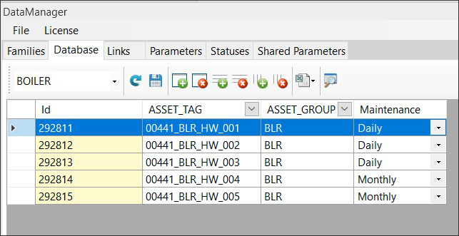
As shown in Figure 3, users can create a database table using the “Add Table” icon and name the table. They can populate the table by selecting the desired element rows from the “Families” tab using their ID, then choose the “Add Rows” icon under the “Database” tab to import the selected elements. The selected rows will then be added to the database table. To remove the tables created, users can select the “Drop Table” icon. The tools from the top bar can be used to modify the table. Users can add new rows using the “Add Rows” tool or can remove the existing rows using the “Remove Rows” tool. The same process can be used to add or remove columns using their respective tools. If users decide to enter data manually into the table, they should click on the “Save” icon to save the information entered, otherwise, data will be lost.
Similar to the “Families” tab, tables in the “Database” tab allows the user to select a field in any database table to highlight the element in the model view, or select the graphical element in the model and using the “Find Selected Element” tool to find it within the table.
Any database table created can be exported to an Excel spreadsheet by using the “Excel” drop down menu and selecting “Export” to be saved for record purposes and shared with others, or for editing (adding or deleting) the information in the table.
One shortcoming to this process is that the exported table has to have a column containing a unique parameter value associated with each model element in the table. The unique parameter could be an asset or equipment name or any other value that identifies the element to the user in the external spreadsheet to allow for entering corresponding element data. Given that Revittools doesn’t yet allow existing element data to be extracted from the model, users have to manually enter this unique parameter value for each element before exporting. This could be a tedious and time-consuming process and hopefully will be addressed in future revisions.
Once the spreadsheet is modified and updated, it can be imported back to Revit using the “Excel” drop down menu. The user has two options for importing the document back into Revittools (Figure 4). The first option is “Import to empty table” which will clear out the existing table and replace it with the updated data imported. The second option is “Update current table” which will modify the existing table by adding new data imported to current existing data in the table. To use the second option, the user should first create the new columns that will receive the new data added in the external Excel spreadsheet. The headings of the columns in Excel should match the names defined in the columns in the Revittools table.
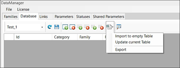
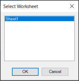
After selecting one of the options, the user should select the desired sheet from the Excel file from which they want to import (Figure 5).
After completing a table under the “Database” tab, there are two options for moving forward with the workflow. One option is to use the “Parameters” tab to create element parameters and assign them to elements of different categories in the model. In this case, the user will have to enter a value for each parameter assigned directly in Revit. The second option utilizes the “Shared Parameters” tab and allows the user to embed parameters and their values defined in the various tables of the “Database” tab to elements of various Revit categories.
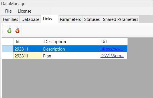
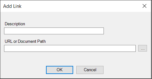
The “Links” tab (Figure 6) is used to link external documents and URLs to elements of the BIM model, enabling the model to be connected to external sources. To do so, users should first select a single element from the “Database” tab, then click on the “Insert Link” icon. After entering the description and URL or Path (Figure 7), the link will be created. Each element in the “Database” tab can have multiple links. The links created can be removed using the “Remove Link” tool.
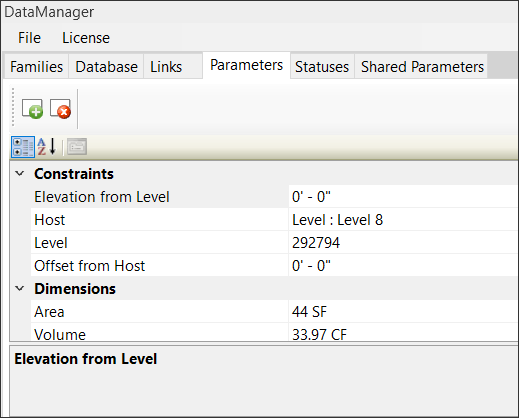
The “Parameters” tab (Figure 8) displays some of the parameters and their values for any user-selected element from the model. By double-clicking on a value under the “Database” or “Families” tab, some of its properties will be displayed under the “Parameters” tab. There is a need for improvement in this area since not all properties under the Properties window are presented here. If improved, this tab can be beneficial by presenting all the properties related to an element in a single tab.
By selecting the “Categorized” icon, element properties are displayed based on the categories in the Revit Properties window. By selecting the “Alphabetical” icon, the properties are organized in an alphabetical order.
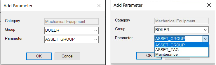
Users can use the “Add Parameter” tool to add one of the columns in the “Database” table as a property to a category (Figure 9). When an element is selected, its category is automatically selected and locked. The “Group” presents the name of the table under the “Database” Tab and the “Parameter” presents the name of the column in the selected table. All the tables created under the “Database” tab are present for creating a new parameter under this tab. However, the value entered for that property is not assigned to the element when using this option. The only issue is that, when a user creates a parameter using Revittools, the new parameter will be presented under the “Data” heading in the Properties window. As mentioned above, this heading is not presented under the “Parameters” tab and therefore, after creating the parameter, the user will not be able to see it under this tab and is not able to delete the created parameter.
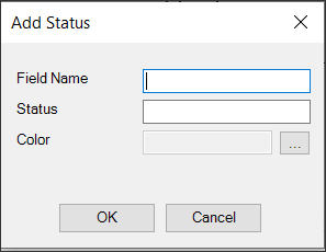
If the user is familiar with Navistools for Navisworks (also from Codemill), this is a similar feature that allows creating different conditions (e.g., shipped, delivered or installed) and assign these conditions to the elements in the Revit model using a color scheme legend. This allows users to track the status of the element based on the defined parameters and by the color exhibited. To do so, users should click on “Add Status Rows” tool and select field name, condition (Status), and color to create a new status (parameter), as shown in Figure 10.
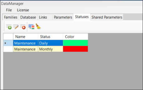
The colors assigned to different conditions can be modified using “Edit Status Row” tool. Also, users can remove a single status using “Remove Status Row” tool or can remove all created statuses by selecting the “Clear Statuses” tool.
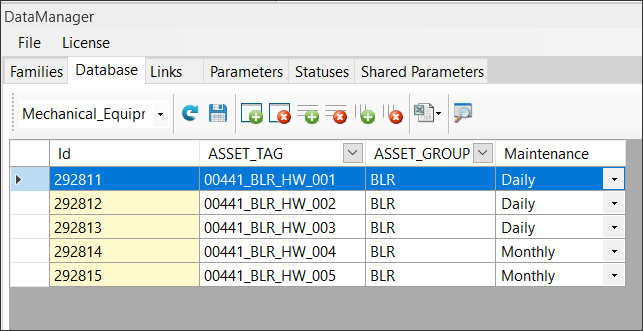
After creating the desired rows under the “Statuses” tab, users should create columns under the “Database” tab with the same parameter name and assign a condition for each element. For example, after creating the Maintenance parameter under the “Statuses” tab and creating two conditions of daily and monthly for it, a column with the same name should be created under the “Database” tab (Figure 12). One of the conditions created for maintenance can be assigned to each element.
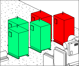
After finishing this process, the colors will be assigned to the assets by first selecting the desired rows under the “Statuses” tab and then selecting the “Displaying Statuses” tool. As shown in Figure 13, coloring the model based on the condition of different elements allows the user to visually track the elements.
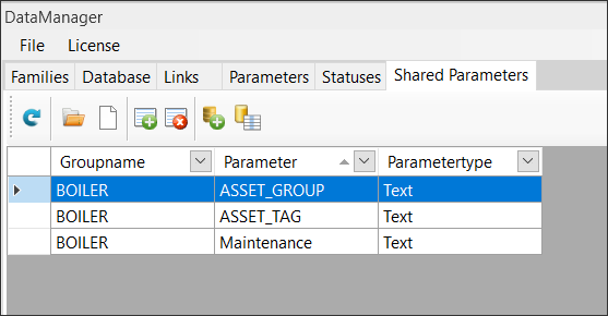
Revittools allows users to create shared parameters using various options and assign the parameters to model elements at the category level. The shared parameters created are presented in the table under the “Shared Parameters” tab (Figure 14). The “Groupname” is the name of the table if the “Create Shared Parameters from Database” option is selected. The “Parameter” heading presents the different shared parameters added to the table. The “Parametertype” presents the type of the shared parameter.
There are some options for adding shared parameters. The first option is to use an existing shared parameters file to allocate the parameters to the tab. Users can access these files by selecting the “Open Shared Parameters File” tool.
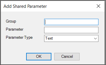
A second option is to create a new shared parameter file using the “New Shared Parameters File” tool and use it for adding shared parameters. The third option is to create a new shared parameter by selecting the “Add Shared Parameter” tool and entering the parameter name and type (Figure 15). The last option is to use the columns in the “Database” tables as shared parameters and add them to this table. To do so, users should select the “Create Shared Parameters from Database” tool. User can remove the shared parameters created using the “Remove Shared Parameters” tool.
The advantage of the fourth option is that it allows the users to add the values in the “Database” tables and assign them with the shared parameters to the elements instead of creating the shared parameter, selecting each element, and assigning the value to it. However, this option needs improvement. Currently, when selecting this option, the shared parameters table is populated with all the existing columns in all the tables under the “Database” tab. In other words, if a user has three tables with three columns in each, nine shared parameters will be added to this tab. There needs to be an option to allow the user to select specific columns from selected tables and only transfer those to the “Shared Parameters” table.
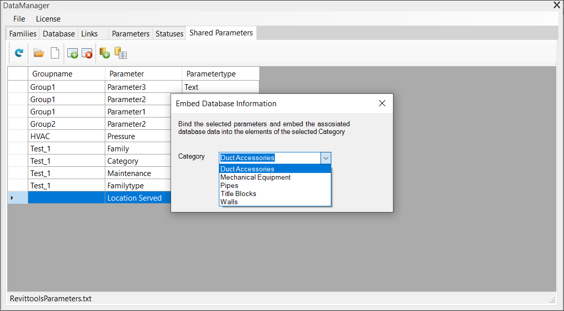
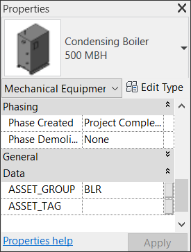
Shared parameters can be embedded to one Revit category at a time (Figure 16) using the “Embed Database Information” tool. Embedded shared parameters are listed under the “Data” heading in the properties window in Revit (Figure 17).
There are some issues with this process. First, the shared parameters can only be assigned at the category level which reduces the value of filtering the table under the “Families” tab. Second, it only creates instance parameters and there is no option for creating type parameters. As a result, users must enter a value multiple times for elements of the same type which is time consuming. Third, there should be a column which allows the users to identify the category for the parameters listed under this tab.
Adding Existing Data from the Model to the Database Table
Currently, Revittools does not have an option for adding existing parameter data from the model to the “Database” table. Adding this option will allow more value to the application.
Presenting All the Parameters Under the “Parameters” Tab
The “Parameters” tab only presents some of the properties associated with an element. It will be more beneficial if it can present all the properties associated with an element.
Columns Added to the “Shared Parameters” tab from the “Database” Tab
When populating the “Shared Parameters” tab using the “Database” tab, all the columns from all the tables defined under “Database” tab are added to the “Shared Parameters” tab. There should be an option to allow the user to select the desired columns from specific tables.
Embedding Shared Parameters at Family Level
The only option offered by Revittools for embedding user-defined shared parameters is at the category level. That does not give the flexibility in embedding parameters to the model elements since come parameters should be assigned at the family or type levels.
 Walid Thabet, Ph.D., is a 22+ year faculty member of Virginia Tech and has been teaching and developing construction and construction management courses at the undergraduate and graduate levels. His current research agenda focuses on Virtual Design and Construction (VDC), Construction Innovation and BIM for Facility Management (BIM-FM). Dr. Thabet leads the Virtual Facilities Research Lab (VFRL), offering emerging CRE leaders hands-on experience in technology development and practical application as well as access to industry through both corporate and academic partnerships. His recent projects involve collaborative research efforts with several A/E/C industry partners to expand knowledge of BIM and explore emerging software tools and technologies including Augmented Reality.
 Mahnaz Ensafi is a Ph.D. student in the Department of Building Construction at Virginia Tech. She holds a Masters degree in Environmental Design from Texas Tech University. Her research interests include Building Information Modeling (BIM), Virtual and Augmented Reality and its applications for facility management, and construction safety.
AECbytes content should not be reproduced on any other website, blog, print publication, or newsletter without permission.