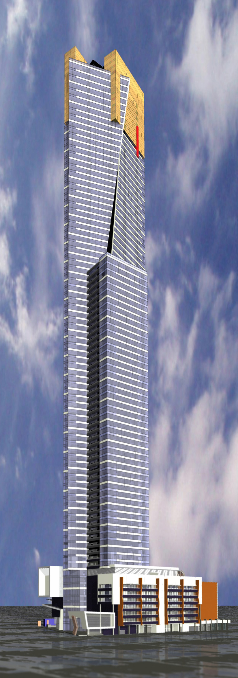
The soaring image of the Eureka Tower project, shown in Figure 1, is probably a familiar sight to most AEC professionals who have been following presentations and articles on building information modeling (BIM) this past year. Standing 92 stories tall with a total height of 300 meters (984 feet), the Eureka Tower located in Melbourne, Australia, is not only the tallest residential building in the world, it is also one of the largest projects to be designed using the principles, methodology, and processes of building information modeling.
How exactly was it done, and what was the technology that was used? What were the unique challenges involved in designing this project? What was the motivation for using BIM and how well did it work? Was the BIM methodology used by the extended design team? Is the BIM model being used for construction and does it figure in the plans for the operation and maintenance of the project? These are intriguing questions and can serve as a valuable guide for the adoption and implementation of BIM by other AEC firms across the world for their own projects. I had the opportunity to find the answers to many of these questions recently when I attended a presentation in San Francisco by David Sutherland, Director of Planning at Fender Katsalidis Architects (FKA), the Australian firm that designed the Eureka Tower project. My findings are presented in this AECbytes feature article.
Let's start with a brief overview of the project as well as the firm that designed it.
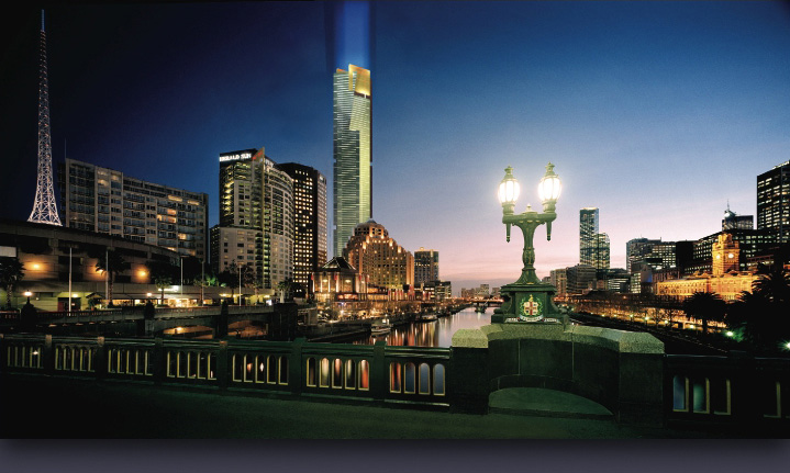
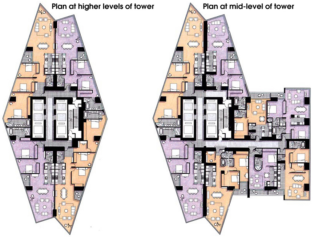
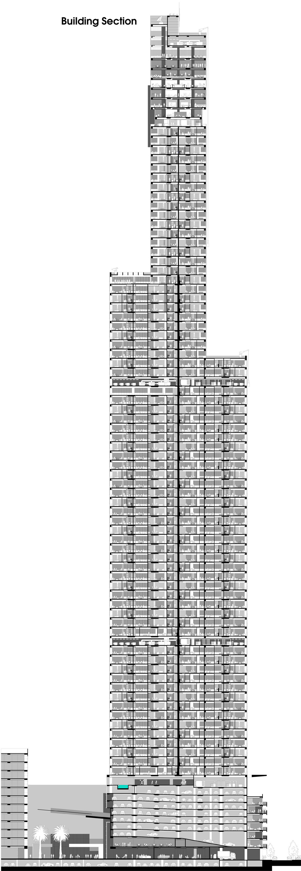
The Eureka Tower is located within the Southgate precinct of Melbourne, adjacent to the Yarra River, in a landmark neighborhood comprising the Southbank Promenade, the Arts precinct, and the Crown Casino and Entertainment Center (see Figure 2). In addition to the residential tower that houses the apartment units, the building includes a ten-storey podium complex containing a parking lot and retail and office facilities, a 3 star hotel, and an observation complex at the top featuring public areas. The apartment sizes range from less than 100 m2 (1076 ft2) to full floor penthouses of up to 640 m2 (6890 ft2). Figure 3 shows two plans and a section through the building.
The project was commissioned by Adam and Daniel Grollo, Tab Fried, and Nonda Katsalidis, in a joint venture—Grocon Riverside Developments and Michelmersh—formed specifically for the Eureka Tower project. Construction on the project commenced in mid 2002, and it was scheduled for completion in 2005. Out of a total of 92 floors for the tower, to date the core has been constructed to level 64, and floor slabs to level 46. Final completion is still expected in the fourth quarter of 2005. The total budget for the residential tower is approximately AUD 400 million (USD 280 million). The overall project budget for the tower and the podium retail, car-parking, office, and hotel is approximately AUD 500 million (USD 354 million).
It comes as somewhat of a surprise to find that FKA, the architectural firm that won the commission for the project, is quite young and relatively small—it was founded in 1997 and has only 30 people. The principals of the firm, however, are very experienced and had been involved in other practices with each other over the past twenty-five years before forming FKA. Since its inception, the firm has established a reputation for itself with its award-winning high-rise residential, commercial, and public designs in several Australian cities and more recently also in Hong Kong, Malaysia, and Shanghai in China. It is known for designing cutting edge buildings with sound functional planning. In addition to the Eureka Tower, some of FKA's other well-known projects in Australia and Asia include the Ian Potter Museum of Art, the Republic Tower, Bendigo Art Gallery, and HM@S Beach Apartments.
While the term "building information modeling" had not yet been coined at the time the design of the Eureka Tower got underway in 1998, FKA had committed to the use of ArchiCAD which offered the 3D object-oriented, database-driven approach to building design they were looking to implement. The firm had long been frustrated with the limitations of 2D CAD software, at its mimicking of manual drafting, tedium, lack of accuracy, and its generic nature that did not allow it to address the specific needs of architects. Being exposed to the benefits of powerful database tools only increased this frustration and motivated technology leaders within the firm like Sutherland to push the transition to the 3D model-based approach.
The Eureka Tower project was seen as the ideal project to make this transition. FKA wanted the design process to resonate with the modern and elegant nature of the project, and be forward-looking rather than traditional. The size of the project also played a critical role in this decision. Recognizing that design errors account for a major portion of the costs associated with construction errors as well as maintenance costs, which would only be magnified in such a large project, FKA wanted to minimize design errors as much as possible. The 3D building modeling approach was seen as a critical means to achieve this goal, and the firm decided to adopt it in a "pure" way: by designing entirely in 3D and deriving the documentation as a by-product.
The fact that the firm had very few licenses of 2D CAD drafting software made the transition to 3D modeling software relatively easier, with little inertia on the part of the firm's employees. The principals of the firms were also convinced about the benefits of the model-based approach in meeting the needs of streamlined construction programs within an environment of strict financial and planning controls.
With regard to the decision on which software to implement, the choice of ArchiCAD was made based on Sutherland's exploration of model-based solutions in the early 1990s before the formation of FKA. At that time, both Autodesk Architectural Desktop and Autodesk Revit were still into the future, and the only other available solution, MicroStation Triforma, did not match up to ArchiCAD's ease of use. This was seen as a very important criterion that would help avoid the segregation between the "designers" and the "technology experts" and allow everyone in the practice to be able to use the new technology that was going to underlie the architectural process. ArchiCAD was found simple to use yet powerful in what it could achieve. Architects, as opposed to CAD people, could effectively use it with a minimum of training, cutting right across the "cult of the expert." The decision was also somewhat of a personal one for Sutherland, who found from his interaction with the local ArchiCAD dealers and distributors, as well as with representatives from Graphisoft, that they were predominantly from the architectural profession and maintained their interest in building design. He felt far more comfortable discussing with such people issues he had with their software than with those who were less steeped in architectural culture.
Once the decision was made to implement the model-based approach of ArchiCAD, it was deployed right from the beginning of the project, starting with the conceptual design. Massing models were developed of the building and the surrounding context, and assessed in conjunction with physical models of the building form and façade detail. Multiple design options for the building were explored. Sun shading studies were performed to generate shadows and analyze their impact on the surrounding buildings. At the plan level, ArchiCAD was also used to study areas, circulation, egress, site subdivisions, and so on.
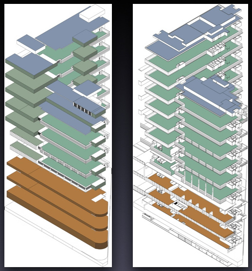
Once the basic building form was finalized, the conceptual 3D model was enriched by designing and adding the details (see Figure 4). At this stage, developing the model was almost like prototyping the building. The model was built storey by storey, using components developed within the application. The model then became the means to also capture the rationale for the design, to explain why it was what it was. This in turn allowed more dialogue and a much higher degree of interactivity in the design process than was possible with traditional 2D CAD.
Because the design was captured and explained to the clients using the 3D building model, FKA found that highly photorealistic rendered images—which are by now commonplace in architectural practice—were not usually necessary. The design team did use Artolantis, a dedicated rendering program that integrates well with ArchiCAD, but it was used in tandem with the design software for exploring design issues, and not just for rendering. Thus, rendered images of the Eureka Tower like the ones shown here are relatively few.
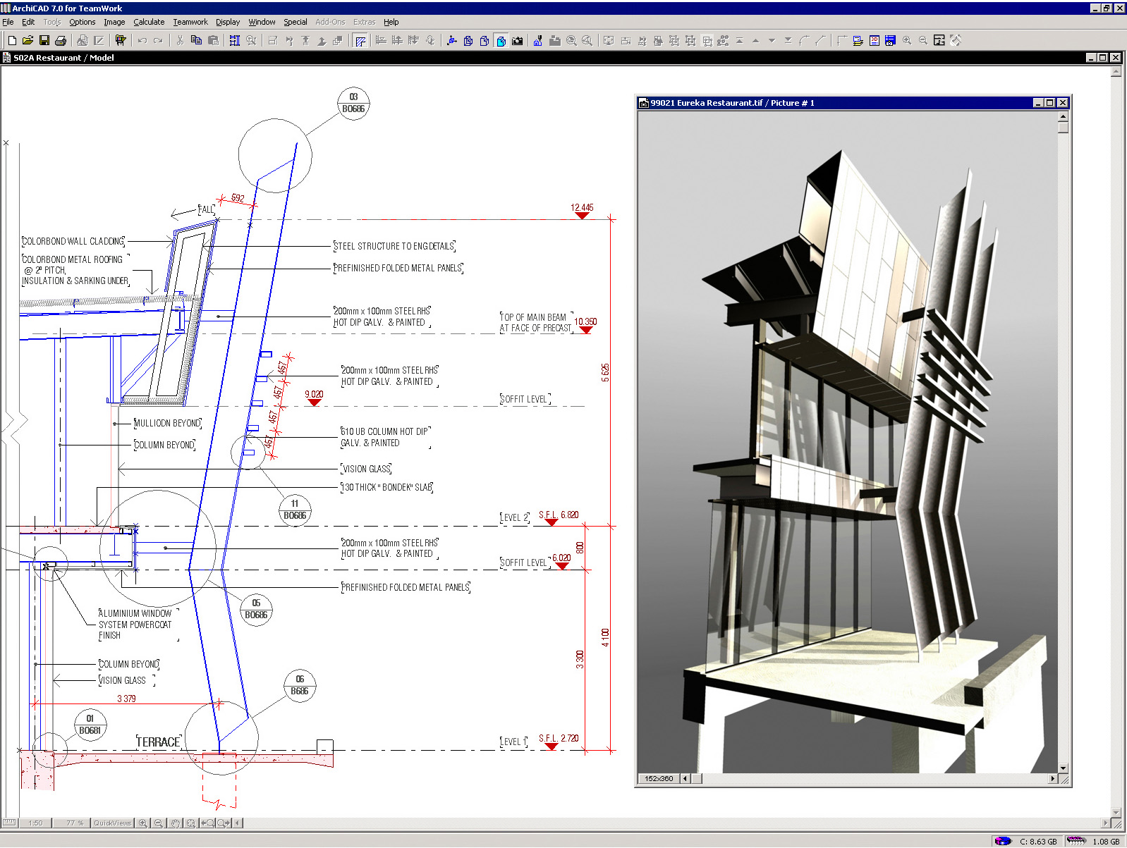
Most of the construction documentation for the project, an estimated 1000 A1 sized construction drawings, was derived directly from the 3D building model. An example is shown in Figure 5. The drawings were further annotated, dimensioned, detailed, and then printed using ArchiCAD's associated plotting utility, PlotMaker. Aspects such as line weight, dashed lines, hatching, and so on are automatically taken care of in the derived 2D drawing, so that relatively little grunt work is needed to finish it. Because each drawing maintains its association with the 3D model, any change in the model automatically updates the drawing, including the dimensions. In a project of this size, these savings in time and the minimization of documentation errors are magnified many times over.
In addition to deriving the construction documentation, the 3D building model was used for several other design and analysis aspects. It was used to study the construction sequencing of the project, again very critical in a project of this magnitude. It was useful for the interior design, allowing material combinations and furniture layouts to be explored. Once the interior layouts were finalized, the model allowed the fixtures to be automatically checked against the penetration documents. The model could not be used for cross-disciplinary collaboration, however, since most of the consultants and other members of the project team were still using the 2D CAD methodology. Therefore, only the 2D drawings were shared with the extended building team, not the 3D model. With regard to the use of the model for future facilities management, operation, and maintenance of the building, no firm plans have been made yet, although the availability of the information-rich model should certainly make this a compelling option after the construction has been completed.
Most architectural practices seeking to transition from CAD to BIM would probably start by testing it out with small pilot projects. In contrast, FKA plunged right into the deep end of the ocean by using its largest project to date to make the transition. It not only had to develop a new design methodology and train the 15 to 25 member project team in the use of the applications following this methodology, it also had to deal with the special challenges involved in the design of such a huge project using the BIM approach.
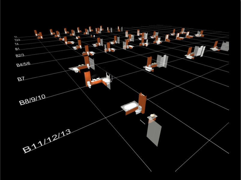
Having the entire building model in one file would have been too unwieldy. To ensure that the file sizes were within reasonable limits, the full model was divided into several different sub-models. This subdivision was facilitated by a hot-linking capability in ArchiCAD that was luckily introduced just when FKA had commenced on the detailed design development of Eureka Tower. (The version of ArchiCAD that was used was 6.5; the current version is 8.1.) This new capability allowed subordinate elements to be created in one file and hot-linked into another file. That file, itself, could further be linked into another file, with the choice of including or not including the nested information. So, for example, a wet area fixture could be designed separately in one file, then hot-linked into a typical apartment file, several of which could, in turn, be hot-linked into the tower sub-model (see Figure 6). Similarly, hot-linking was used to build up the other sub-models, including the podium, façade, primary structure, and so on. All these sub-models were then hot-linked to form the full Eureka Tower model, which was 330 MB in file size and took a full 20 minutes to load. Needless to say, the full building model was used sparingly, and most of the design work was done using the sub-models.
This entire hierarchy of models and sub-models added up to a very complex arrangement of information that had to be very carefully structured and managed. However, the effort was well worth the benefit. Not only did this allow parts of the building to be isolated into smaller and simpler models that could be used to study and design variations, it also allowed components and assemblies to be designed once and re-used across the project. Any change made in a sub-model would be automatically reflected in all the parent-level models that the sub-model was hot-linked into. One member of the design team acted as a dedicated "Model Manager" who was responsible for checking the correctness of the full 3D model at all times.
With regard to workstation resources, FKA was able to implement the Eureka Tower project on standard computers that architects can afford. It did, however, need to upgrade its network, hubs, and graphics cards to be able to work more efficiently. The firm's resources were utilized to their fullest capacity, and conversely, the BIM approach was implemented to the fullest extent of the available computing power and time.
In the course of implementing the BIM approach for the Eureka Tower project, FKA has found that its benefits extend far beyond just the project in which it is used to the firm as a whole. The advanced use of technology has flattened the traditional hierarchical management structure and reduced the divide between the older design principals and the younger technologically-savvy staff. BIM allows for a process in which there is no division between design and documentation, and therefore eliminates the need for dedicated draftspeople who only do documentation. Since the documentation is now achieved as a byproduct, everyone involved in a project concentrates on the design, and is required to collaborate effectively with the other team members. Thus, BIM enhances cooperation rather than segregation between the employees of the firm.
With regard to the project itself, the ability to visualize the building in 3D leads to a much better understanding of the design. Multiple design options can be easily explored, and subjected to a higher degree of analysis and evaluation than would have been possible with traditional 2D CAD. The increased focus on analysis allows better decision-making and leads to a functionally sound building. The practice of architecture itself becomes like a performing art and is a lot more enjoyable.
In the case of the Eureka Tower project, the use of BIM did not extend to other disciplines since the consultants were not yet ready to give up their standard 2D CAD based processes. The benefits would have been even more remarkable had it done so.
One of the most frequent questions asked by AEC professionals when building information modeling is discussed is: "Who will pay for the extra effort to develop the model?" FKA has not let issues such as these hold them back from what they see as the most logical means to design a building using the capabilities of the technology that is currently available. It now sees BIM as the standard way of doing business within the firm and does not expect to receive a higher compensation than its regular fee for its implementation of BIM. The internal benefits have been found to be well worth the extra cost and effort, even for the first project. Subsequent projects should be able to reap the same benefits with much less cost and effort.
I would like to thank David Sutherland of FKA for taking the time to communicate with me at depth about the Eureka Tower project, and for supplying all the images used in this article.
Lachmi Khemlani is founder and editor of AECbytes. She has a Ph.D. in Architecture from UC Berkeley, specializing in intelligent building modeling, and consults and writes on AEC technology. She can be reached at lachmi@aecbytes.com.
AECbytes content should not be reproduced on any other website, blog, print publication, or newsletter without permission.