


This article provides a first glimpse into ARCHICAD’s recently renovated Stair tool, which was overhauled in ARCHICAD 21 and has been further refined in ARCHICAD 22. This overhaul was accompanied by the new Railing tool, but for now, we’ll focus on the getting to know the Stair tool.
First, a quick thanks. In late October of 2018, BIM6x held their inaugural ARCHICAD by the Beach (https://www.archicadbythebeach.com/) event in Cabo San Lucas, Mexico. This week-long VIP training event brought the best ARCHICAD trainers to avid ARCHICAD users, in a gorgeous setting. One of those trainers was Marta Molnar, from GRAPHISOFT headquarters. Marta has been deeply involved in the design of the Stair and Railing tools and is one of the top experts on the subject. I’d like to thank Marta for providing much of the insight and information for this article.
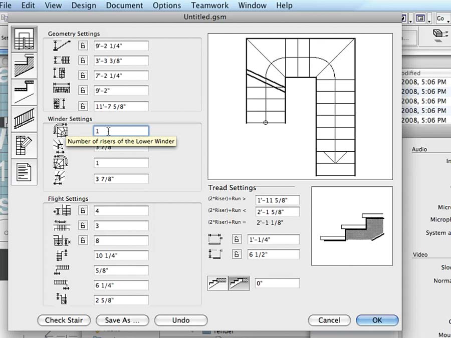
So, was the Stair tool change really that big? Yes, it was. For years, ARCHICAD users struggled with a mix of parametric objects and the tedious and rather frustrating StairMaker tool. It seemed to be public enemy number one for ARCHICAD users around the globe. Users complained and GRAPHISOFT listened.
After more than three years of development, GRAPHISOFT finally revealed their biggest development project since Teamwork, the new Stair tool: a next-gen design tool that extends architects’ design creativity with automatic design validation against human ergonomics — on the fly. This means ARCHICAD’s artificial intelligence algorithms validate thousands of design options in the background and offer architects the most optimal stair designs in the building context to choose from.
The Stair tool lets you create, design and efficiently document any typical or unique Stair that can be devised by an architect, at any design scale. The tool focuses on an intuitive and flexible design process, with graphical input and editing, as opposed to one-click input followed by time-consuming parameter settings. The Stair tool supports compliance with general architectural regulations and individual (e.g., structural or documentation) requirements. Stair structure and finish options reflect construction technology logic.
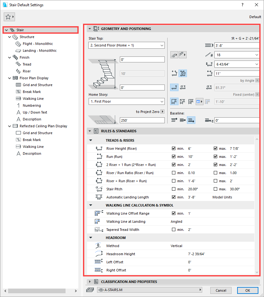
The Stair tool, much like ARCHICAD’s Curtain Wall tool, is a hierarchical element. This means that depending on what is selected higher up in the hierarchy, the options lower in the hierarchy will change. The main Stair element consists of multiple sub-elements, including 3D Model elements such as Flights, Landings, Treads, and Risers, as well as 2D Symbol, Floor Plan and Reflected Ceiling Plan elements. The resulting Stair is a combination of the model as per the designer’s intent and conforming to pre-set rules, and a 2D Symbolic view that conforms to office standards.
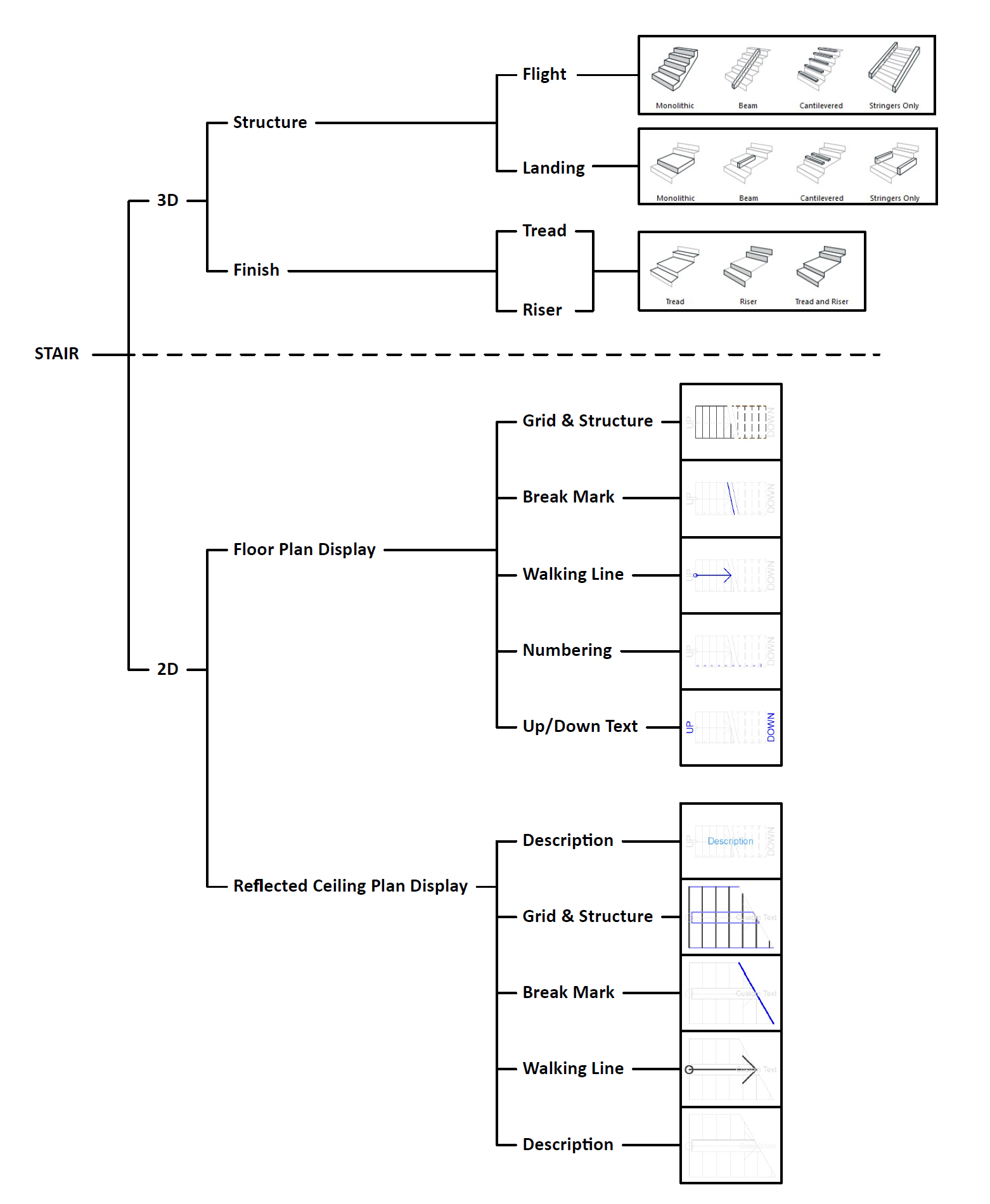
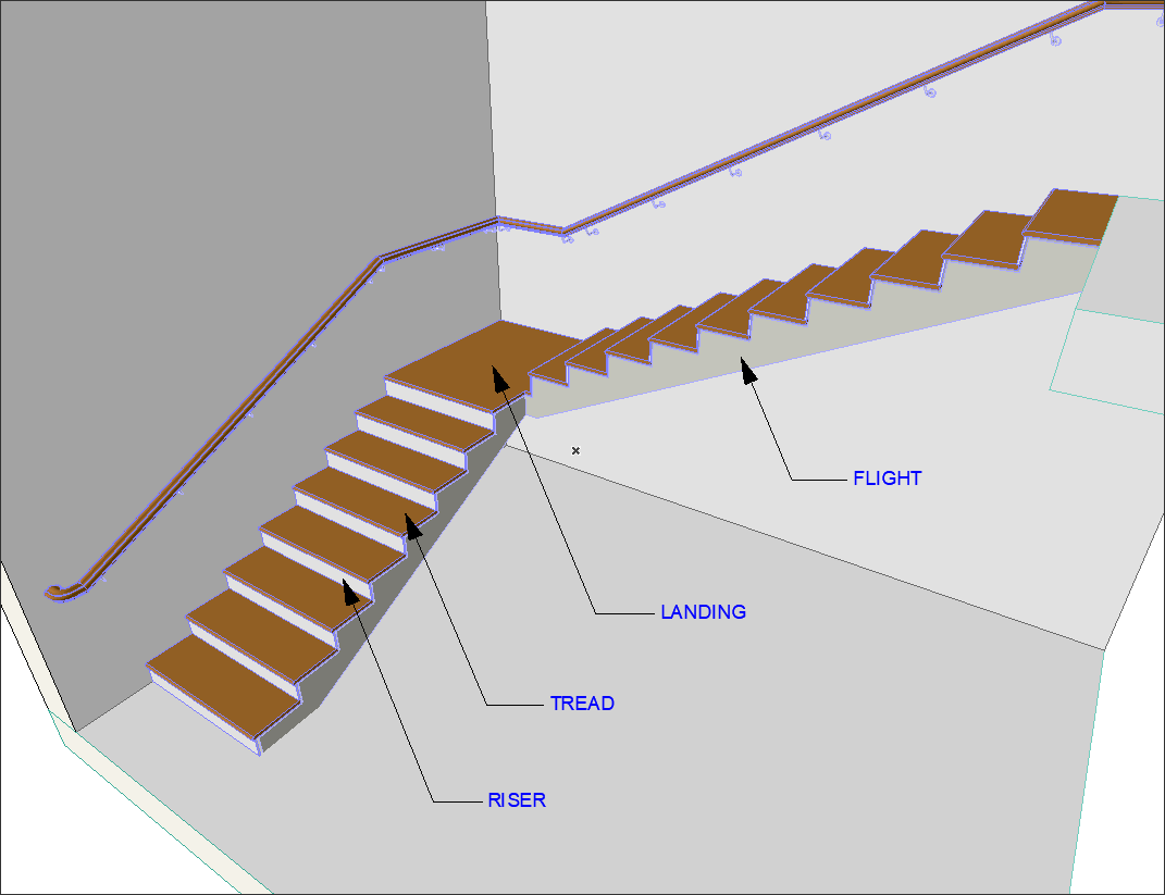
As shown in the image above, the 3D model of a stair is composed of the Structure (which includes Flights and Landings) and the Finishes (which includes Treads and Risers).
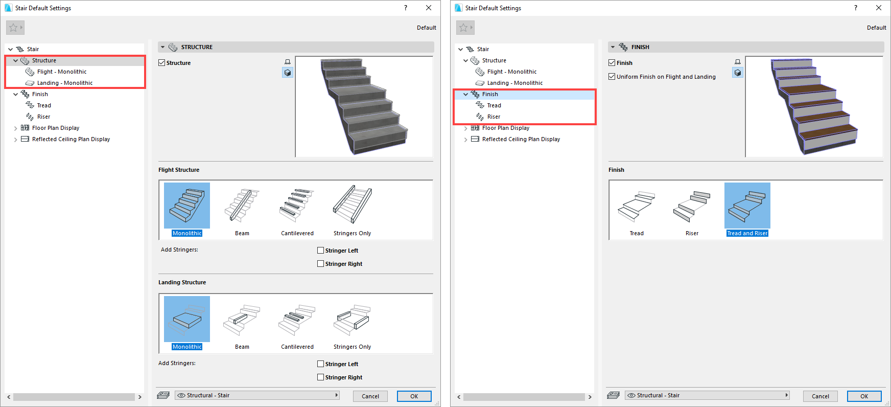
Each of these sub-elements can be set individually and even saved as Favorites making commonly used parts easy to save and recall into full stair systems. For complex sub-elements such as unique beams, stringers, treads, risers, etc., a mix of complex profiles and library parts can also be used.
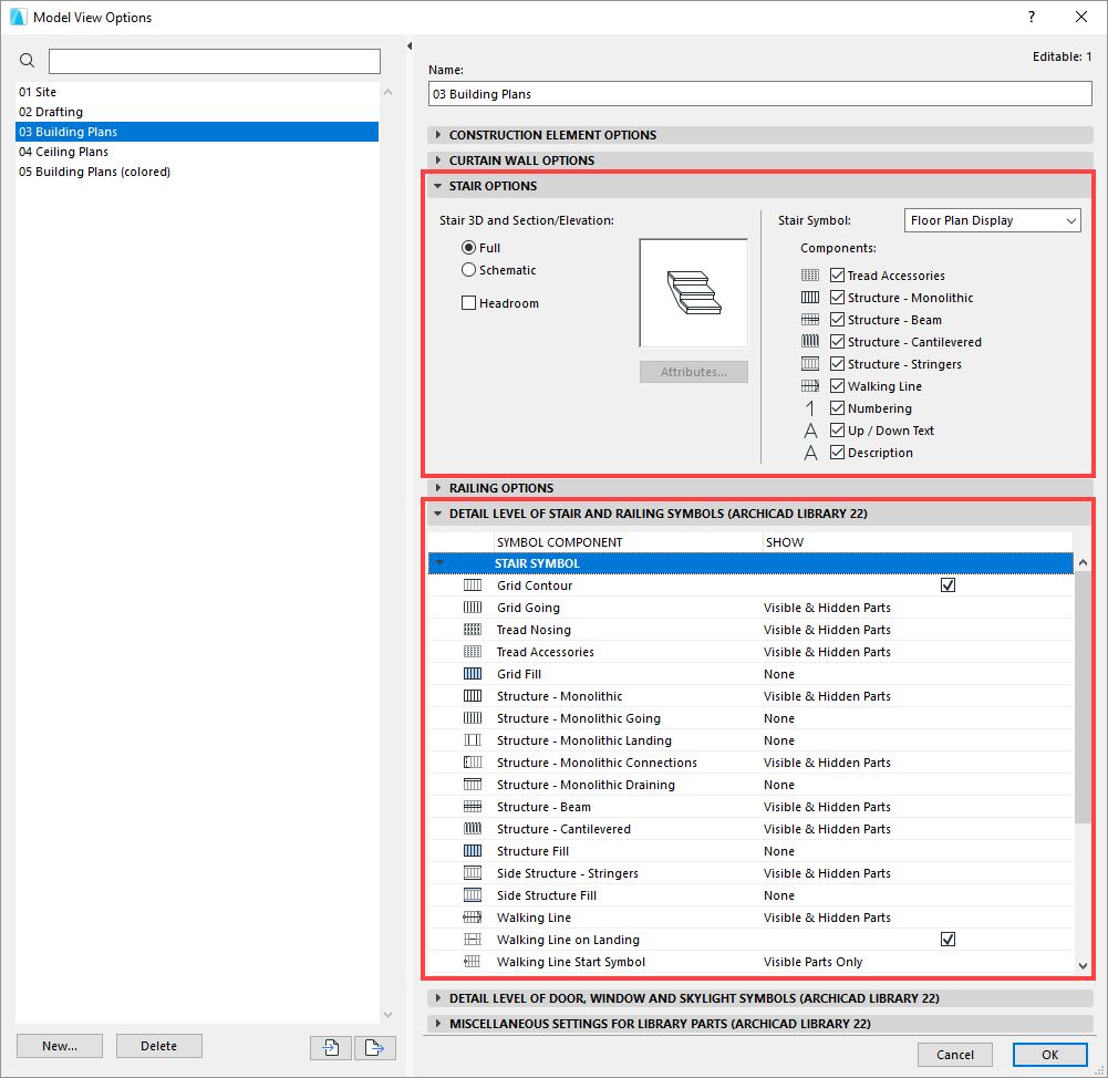
Stairs have two different types of 2D Symbols that are independent of each other: the Floor Plan Display and the Reflected Ceiling Plan Display. This is effectively how the Stair appears in 2D. These settings can be controlled globally by Model View Options or overridden in the Settings dialog.
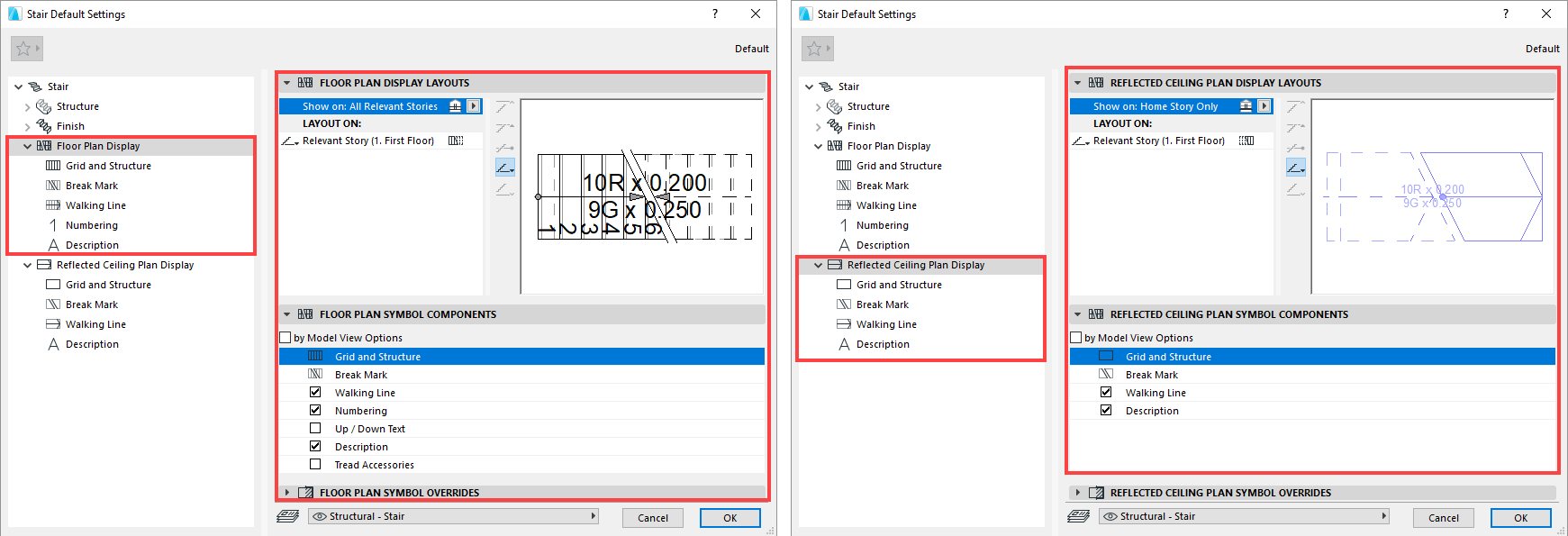
If set by Model View Options, the same Stair can be displayed differently according to the view it appears in. For example, you can show a simple Schematic representation of the stair model along with a simple symbol display in plan for Schematic Design. And for Construction Documentation, you can show a complex Full representation of the stair model, and all the 2D detail and notation in the floor plan.
Once all the components and sub-elements are set, the entire stair can be set, according to the design intent and following pre-set rules and standards, whose accessibility is defined in the Project Preferences. The Settings here include linking the stair to stories, riser and treads options, run depths, automatic landings, winders and turning types, as well as the Baseline, which is important when it comes to placing the Stair.
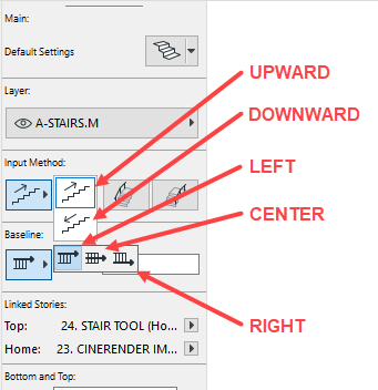
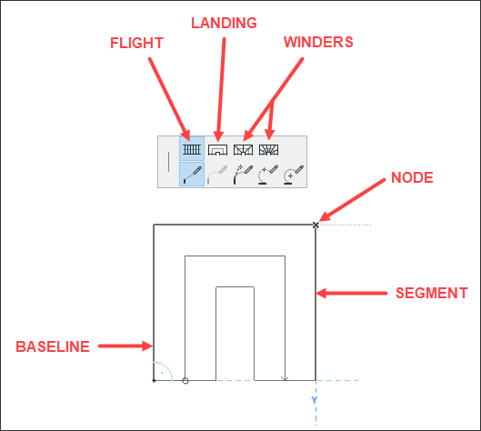
Modeling a stair can be done in the Floor Plan or in the 3D window, and a stair is always placed on its Baseline. A baseline is like a wall’s reference line. Not only it is used to place a stair, but any edits made later are based off its baseline. From the Baseline, the stair can be modeled on the left, center, or right. Another important option available from the Info Box is whether the stair is modeled in the upward or downward direct from the start.
As you model the stair along its baseline (and keep in mind that you can the use Magic Wand!), it can be made up of segments and turnings. When you model a stair, Segments are created between nodes and Turnings are made at the nodes. Segments can include flights, landings and winders. Turnings can include just landings and winders. You simply select the pet palette option for each part of the stair as you create it. You can also edit an existing stair using similar pet palette options.
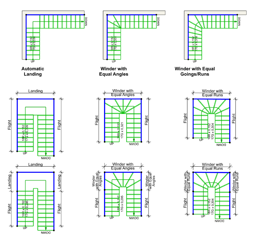
Here are some examples:
Stair design and construction in architecture is limited by regulations that differ by country. These rules usually control the height or length ranges of stair steps, provide limits for the stair pitch, drive minimum widths and lengths of landings and provide detailed construction instructions for winder stairs, for example.
To help users design stairs that meet local regulations, the new Stair tool includes three innovative approaches:
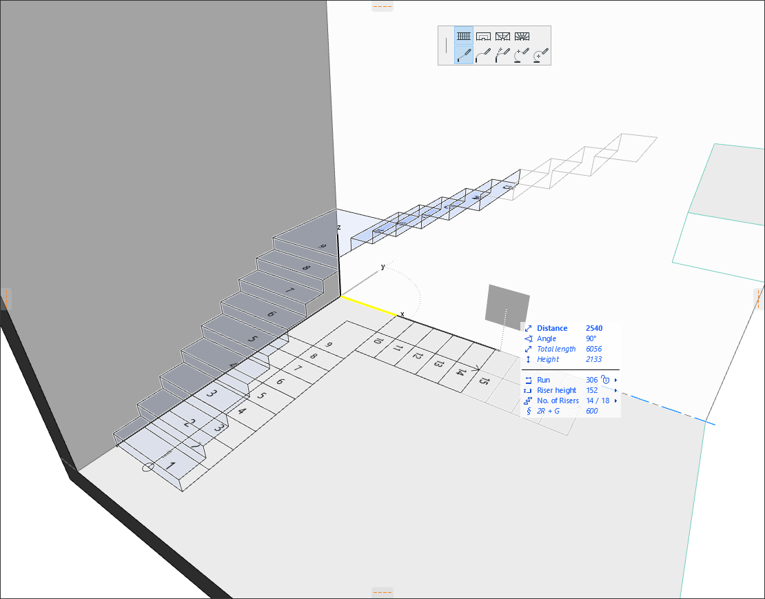
We’ve already covered the rules and standards, and an automatic stair construction algorithm starts from the moment the user starts to model the stair, constructing the stair based on these rules and standards.
During the polyline path input, instant graphical feedback shows what the resulting Stair will look like. To perfectly follow the polyline path, the algorithm automatically adjusts certain geometric values of the stair, within the user-provided ranges in the rules.
In some cases, the input values and the polyline path cannot result in an adequate Stair, yet certain geometric modifications would produce a Stair that does meet regulations. If a conflict or error occurs during input, the ‘Solver’ pops up to help resolve it.
The Solver presents solutions in a graphical interface, showing the proposed changes. They are presented in order of how far they deviate from the originally created Stair — from least to most.
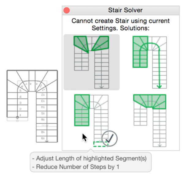
The user can select any solution to see instant graphical feedback of how the modified Stair would look like in context, before accepting it. The Solver can appear not only when drawing a new Stair, but also when an existing Stair is modified (even via a dialog box).
Like Walls, Stairs can be linked to Stories, and so can follow changes in floor height. If the floor height changes only by a small amount, the Stairs will follow automatically (the number of risers will remain fixed, only the height of the risers will increase – within the set Rules). If Story heights change by a significant amount, then ARCHICAD highlights the affected Stairs in the whole project until the user changes any of the given data (e.g,. number of steps or Riser heights).
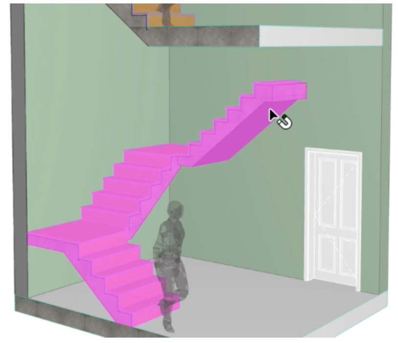
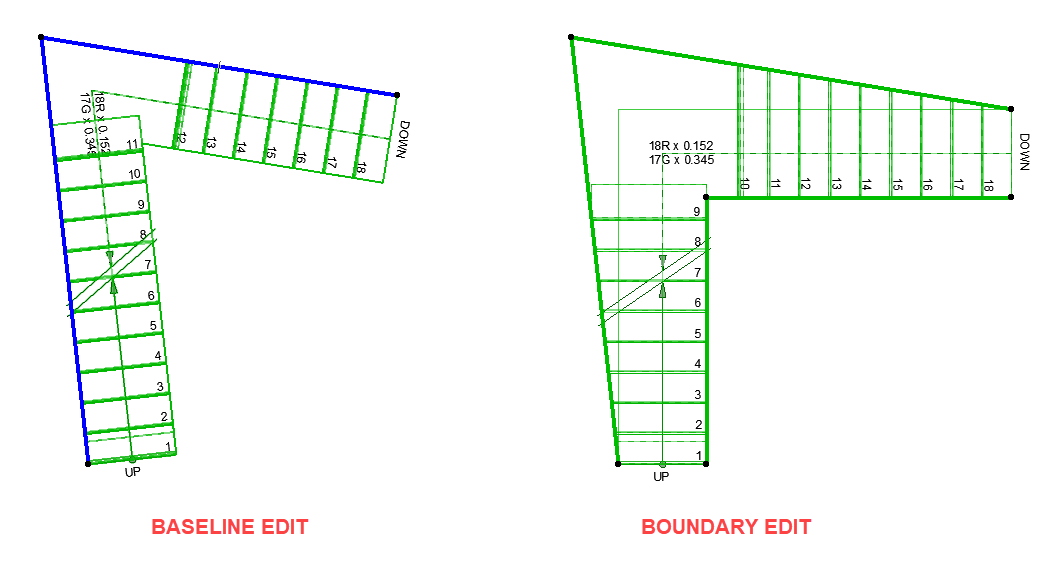
A Stair has a Baseline and a Boundary. Select along the Baseline to see it. Select along the other side to see the Boundary. Or you can hover over the Baseline and hit the Tab key to select the Boundary.

Editing the Baseline’s segments and nodes, we can adjust the type of stair generated. Risers are always perpendicular to the Baseline. Editing the Boundary of the stair changes the shape of the Stair without affecting the geometry of the risers, except for their length.
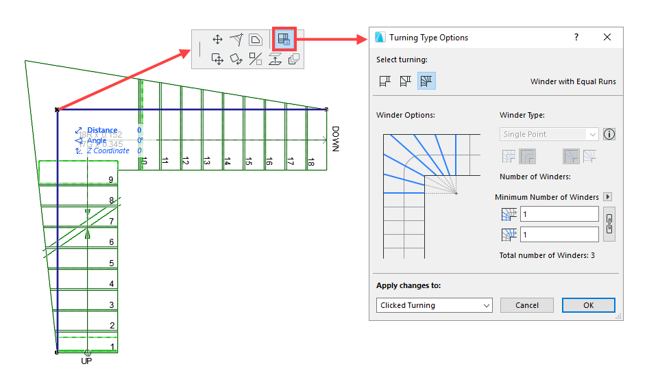
As with any tool in ARCHICAD, the pet palette options differ depending on where you click on the segments or corner/end nodes of the stair’s Baseline or Boundary. These options offer extensive ways to shape and adjust the stair. One important option is to edit a Stair’s Turning Type by clicking on the node of the baseline.
The Edit Mode, similar to ARCHICAD’s Curtain Wall, has been expanded and made available for the Stair tool, to enable easy configuration of sub-elements.
Any placed Stair instance is defined by Stair Settings. However, you can use Edit mode and its dedicated sub-element specific tools to access and change the individual members of a selected Stair, or to add new custom sub-elements to it. Enter Edit mode from Floor Plan, Elevation, Interior Elevation, Section and 3D Window, and you can edit Stair components in all of them, although options will be different for each. And you can remain inside Edit mode even when switching between views.
To enter Edit Mode, simply select the Stair and hit the floating Edit button:
In Edit mode, each sub-element (Treads, Risers and Structures) has its own Settings dialog box, enabling you to change settings individually. You cannot create a new Stair in Edit mode however; the purpose of Edit mode is to provide a deeper level access to the components of an existing, selected Stair.
Once you change the parameters of any selected Stair member in Edit mode, that member is no longer tied to the Stair Settings; it is a Custom member, and its parameters are locally defined, in its individual tool settings dialog box (e.g., Tread, Riser or Structure). Custom parameters are set in Edit mode only. Changing the settings of any selected Stair sub-element in Edit mode will NOT affect the Stair’s Settings.
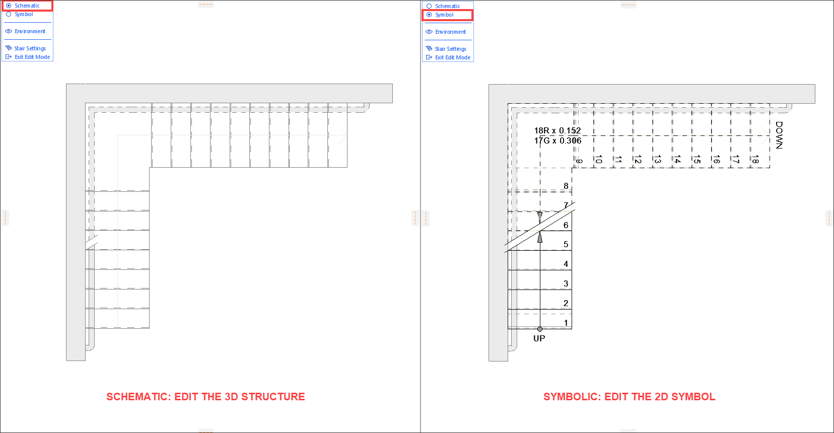
The Stair tool Edit mode in Floor Plan View has two options to display the Stair:
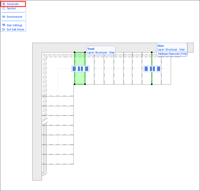
Schematic view shows the Stair as a simplified 3D transparent surface. Use this mode to select 3D Structures, as well as Treads and Risers (use TAB to cycle among multiple highlighted elements). Use Symbol View to access the Stair’s 2D symbol elements (e.g., Walking Line) settings.
In the Schematic view, you can select individual sub-elements, such as individual or collections of treads and risers. Once selected you can edit their settings or polygonal shape.
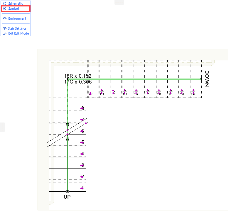
Similarly, when the Symbol view is selected you can select 2D symbolic items such as numbering, walking line, break mark, etc., and edit them individually.
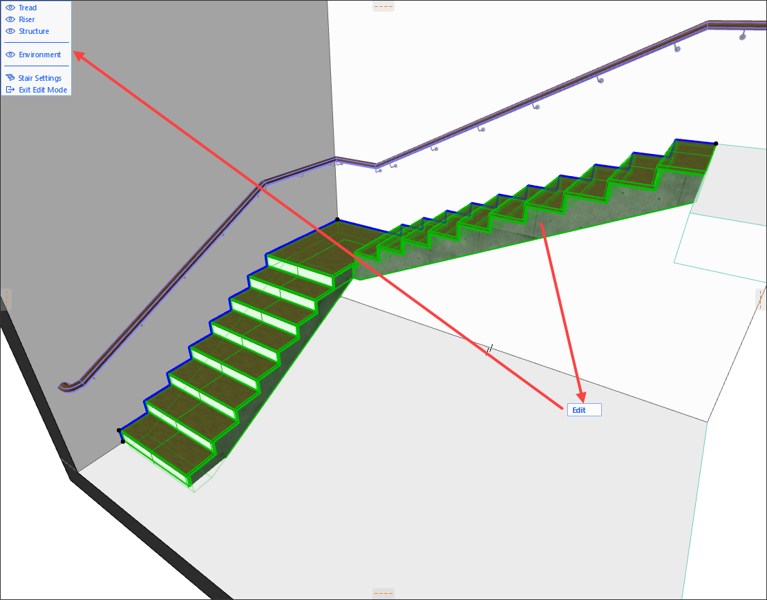
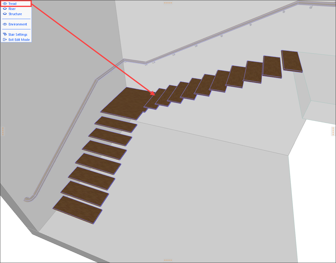
When editing in the 3D Window, you can select and edit the same 3D structure sub-elements just as easily, and there is also the option to temporarily control the visibility of the treads, risers, structure and even the environment (everything that’s not the stair being edited).
The Stair tool in ARCHICAD is very powerful and obviously wonderfully complex! The best way to understand the new Stair tool is simply to go and play with it. There are plenty of resources available, such as the Stair tool YouTube playlist and the Stair-related Help Center articles, to help you along the way.
I hope this basic introduction encourages you to give it a try!
 Link Ellis, formerly of ArchiLINK, is now the ARCHICAD Technical Director at BIM6x. Link is a passionate BIM implementer, specializing in ARCHICAD training and templates. With over 20 years in the industry, he has extensive experience and knowledge of ARCHICAD. Clients have requested his services across the globe including in the USA, Canada, UK, New Zealand, Australia, India, and the Middle East. Link has a long-standing relationship with Graphisoft's ARCHICAD development team and communicates with their technical support team regularly. He is also an award-winning ARCHICAD alpha and beta tester since 2003, member of multiple ARCHICAD forums, and a highly respected and well-liked member of the ARCHICAD community.
AECbytes content should not be reproduced on any other website, blog, print publication, or newsletter without permission.