


Rhino is an amazing tool for modeling and rationalizing complex geometries. Revit is a great tool for storing and managing a BIM project. With the recent release of Rhino 7 (or Rhino 7 WIP) and the creation of the Revit add-on, Rhino.Inside Revit, it is easier than ever before to create BIM assemblies from complex geometries that can be scheduled and sectioned properly.
In this article, I will provide a step-by-step workflow for creating a space frame with complex geometry, using the tools available in Rhino 7, Grasshopper (GH), Rhino.Inside Revit (RiR), and Revit.
The tools that will be used are the following:
If you haven’t used Rhino.Inside Revit before, it may be best to review the installation requirements and instructions. Once everything is installed and ready to go, the Guides and Samples should provide enough of a footing to begin working with Rhino.Inside Revit. If this is also the first time using Grasshopper, then I recommend reviewing these Grasshopper Tutorials and checking out the many instructional videos on YouTube. The Masterclass on Data Trees by David Rutten is particularly helpful for understanding the data structure that Grasshopper uses.
Before starting the process of creating a space frame, I am going to layout the general series of steps that will be taken to achieve this:
This is a general outline for creating a space frame, and there is a lot of flexibility for design and customization. Finding an appropriate balance of automation and designer input will ultimately be determined by the designer, and the features of Rhino.Inside Revit help to empower the designer by providing more means to produce.
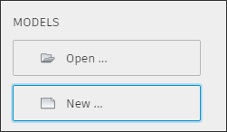
The first steps will be to create a new Revit model and 4-point Adaptive Component:
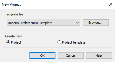
For this example, I chose the Family Template ‘Curtain Panel Pattern based.rft’ which already has 4 adaptive points ready to go.

The first step in the Adaptive Component is to create a profile that will be extruded around the perimeter of the panel, creating the frame. If a frame were created from the profile shown below, it would create a 2”x6” frame.
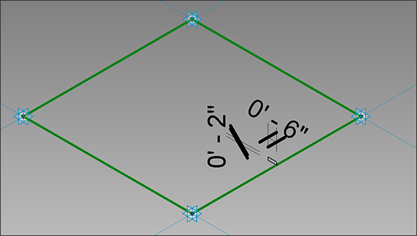
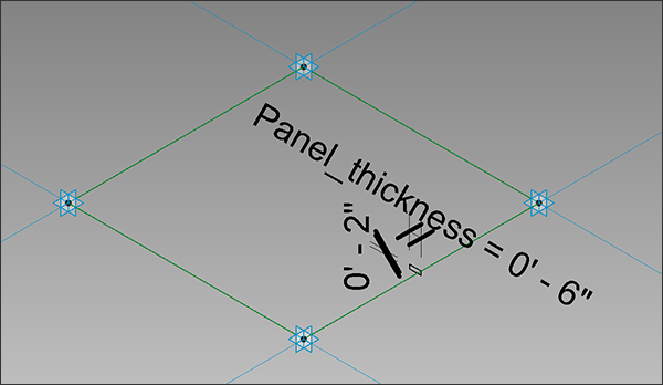
However, in this example, we want to have the ability to modify the thickness of the frame for each instance depending on position and orientation. For this exercise, select the 6” dimension and in the Contextual Modify Tab click the icon to Create Parameter:
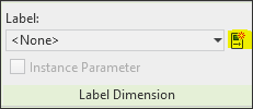
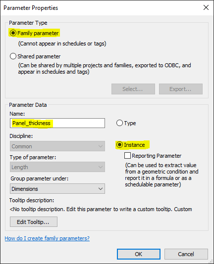
Specify a Name and then make sure that it is a Family Instance Parameter. This will associate the parameter with this Family and allow for each instance to have a different value for the parameter. By default, the parameter will have the same value as the dimension before creating the parameter, but it can be changed later in the settings. For this exercise, all instance parameters will be modified so the default value does not have as much consequence.
Now that the parameter has been created, the form for the frame can be generated by selecting the rectangular profile and the reference lines that connect each Adaptive Point, then selecting Create Form.
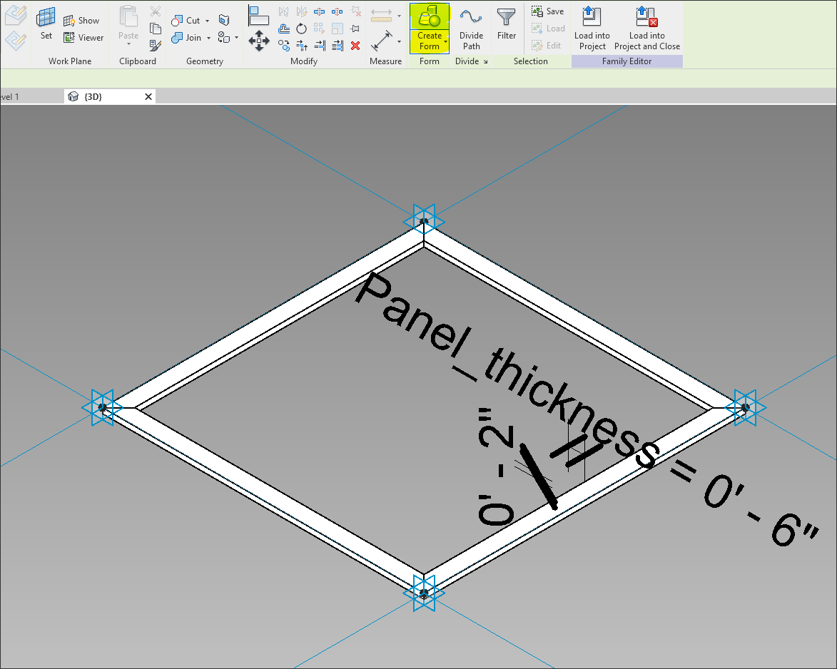
Revit will intelligently extrude the profile along the reference lines.
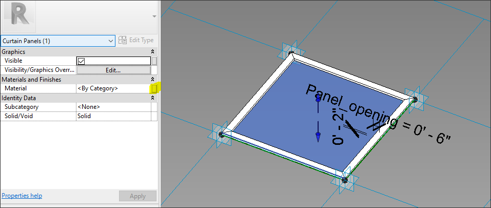
Now, if the Panel Opening parameter is modified, the Family Instance will be changed accordingly. From here, a 2D surface can be created by selecting the reference lines and selecting Create Form.
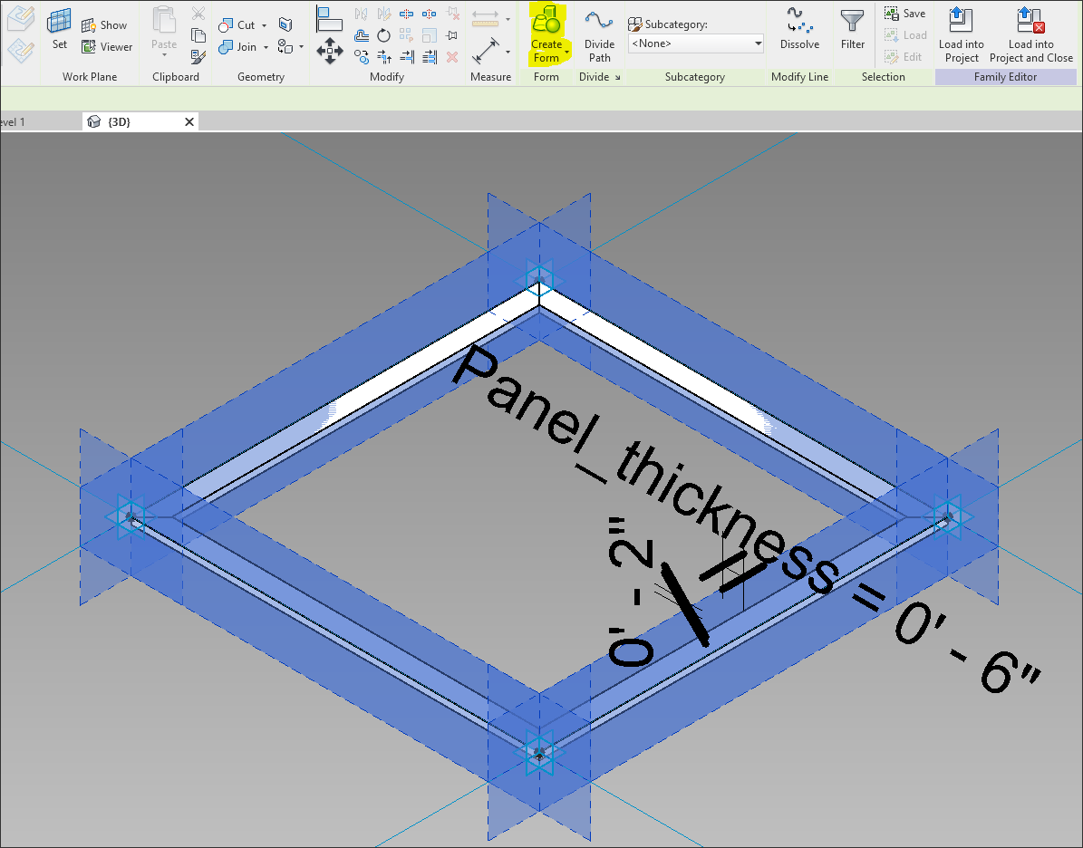
There will be two options available. When creating a proper Adaptive Component, the panel should be modeled as it will be built. For this exercise, however, we will choose simple modeling techniques. After selected Create Form above, two options will be presented:
Choose the 2D surface:

Once created, select the 2D surface and in the Properties panel, click the button all the way to the right for Material to Associate with Family Parameter.
In the dialog that pops-up, click the icon in the lower left corner to create a new parameter:
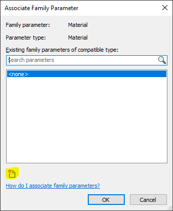
In the Parameter Properties dialog, choose Family, name the Parameter, and choose Instance again. Revit recognizes that this is a Material Parameter and specifies that accordingly.

After creating the Material Parameter, apply it to the 2D surface. This parameter will be driven later by the Grasshopper Script with Rhino.Inside Revit components. Now that a simple Adaptive Component has been created, Insert into the Host RVT. Each instance of this Adaptive Component can now be driven by:
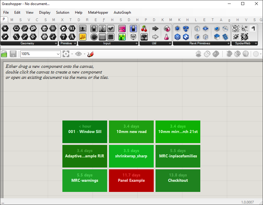
In the Ribbon, navigate to Add-ins and click the Rhino icon:

A new Rhinoceros tab will appear.
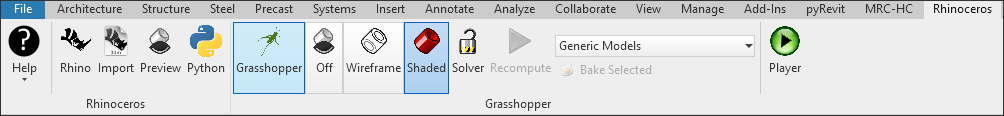
From Left to Right the buttons are:
This example will create a space-frame, but to begin, I am going to load an image (the Microsol Resources Logo) into the image sampler in Grasshopper:
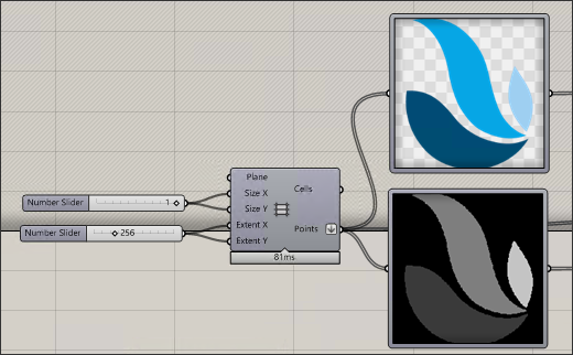
This can be added to Grasshopper by dragging and dropping it into the Grasshopper canvas. This automatically loads an image into the Image Sampler component, as shown above. For this exercise, the image is a PNG has a transparent background. The image is 256x256 pixels, so by feeding in a 256x256 array of points into the Image Sampler, I can extract pixel information from the image.
The top (color) image is extracting the Red, Green, and Blue values of the pixels, and the lower (grayscale) image is extracting the brightness. These RGB values can be used to drive material parameters, such as the Tint color for the newly created Adaptive Component Material Parameter “Glass-mat”.

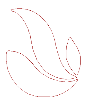
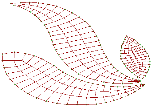
We’ll come back to this, but first, we need to start creating the geometry that will drive the Adaptive Components. Either with a simple script, or by tracing over the boundary of the three (3) distinct objects in the image, closed planar curves can be generated:
These curves can then be subdivided in a multitude of ways in Grasshopper. For this exercise, I am automatically subdividing each curve into Quads (a curve with 4 vertices) with the Quad Remesh Component:

This ensures that I can deconstruct each subdivision into four (4) vertices, which can later drive the Adaptive Components. If desired, I could use the vertices to drive the Adaptive Components right now on the subdivided planar surface, but before I do I want experiment with more Grasshopper components.
Kangaroo provides tools for running physical simulations on Rhino objects. In this example, I want to keep all of the points that lie on the perimeter of the boundary curves anchored to the floor and apply a directional force to all of the remaining vertices and line segments. To do this, all vertices on the perimeter are determined and fed into the Anchor Kangaroo Component (Perimeter Anchor Points, below) which constraints those points in all XYZ directions:
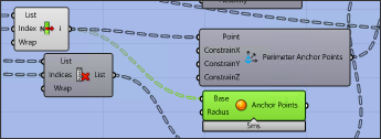
The anchored points are identified as small green spheres in the image below:
In addition to anchoring the perimeter points, each of the line segments must have a way to respond and adapt to the forces being applied. To accomplish this a Spring Force is created from each line segment:
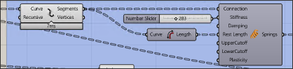
These Springs will generate a response to other forces being applied. Parameters such as Stiffness and Damping, may need to be adjusted so that the simulation converges to an equilibrium. If the forces are too extreme, then the resulting geometry could be crushed or stretched into a form that is undesirable.
Along with the Spring forces, a Unary Force is applied as a lifting force to every other vertex not on the perimeter. This is like creating a catenary curve from a gravitational force, but inverted, so the force is applied in the positive-Z direction.
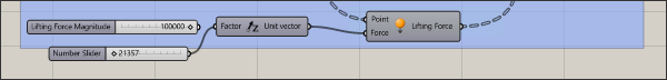
It is important to keep in mind that all of the forces are dimensionless, but their magnitudes relative to each other will determine how the simulation plays out.
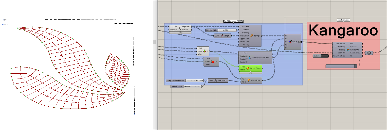
When all the forces have been created and fed into the Kangaroo Solver Component, the simulation can be run. At any time, or once the simulation has come to an equilibrium, the Trigger can be stopped, and the resultant geometry can be reviewed:
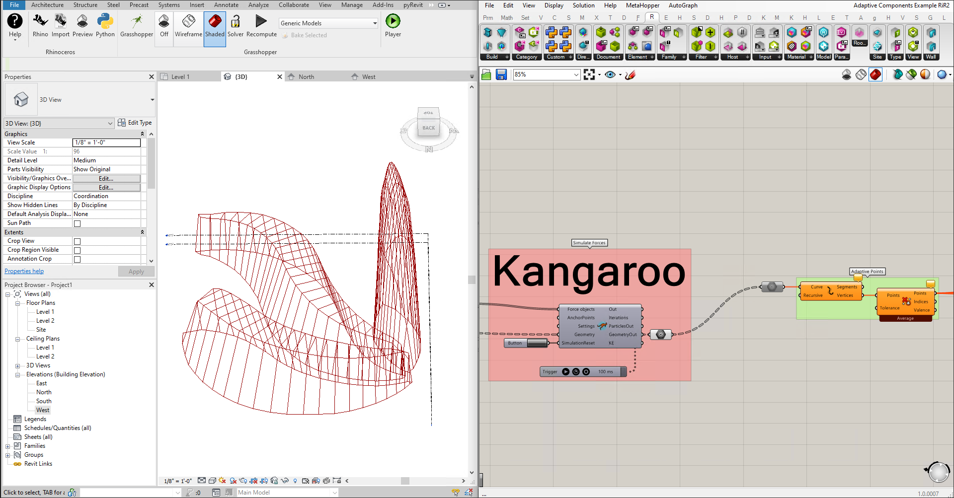
Tweaking the Number Sliders for the forces will change the resulting Geometry. When it reaches a good state, the simulation can be stopped and we have a wireframe spaceframe, with all quads intact flowing out of the GeometryOut node on the Kangaroo Solver Component. The vertices of each quad can now be extracted and used to create new Adaptive Component instances. From GeometryOut, the quads are exploded into points, grouped into fours.
Finally, the data is ready to pass to the Rhino.Inside Revit (RiR) Components, which will serve as the anchor leg of this workflow. With the datatree of points fed into the RiR component Add Component (Adaptive), along with the Curtain Panel Family Type, default instances of each Adaptive Component will be created.
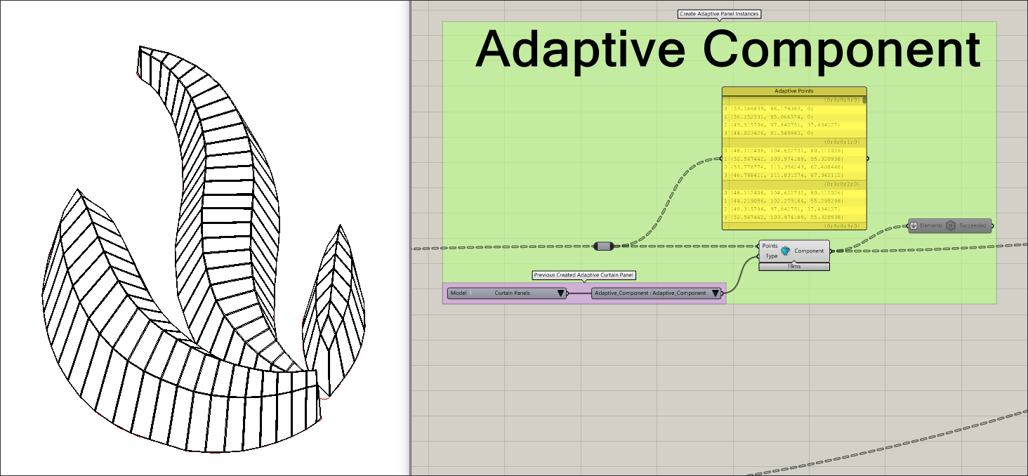
As you can see, each panel that was created has the same thickness throughout (6”). After creation, the parameters controlling thickness can be modified manually, or generatively.
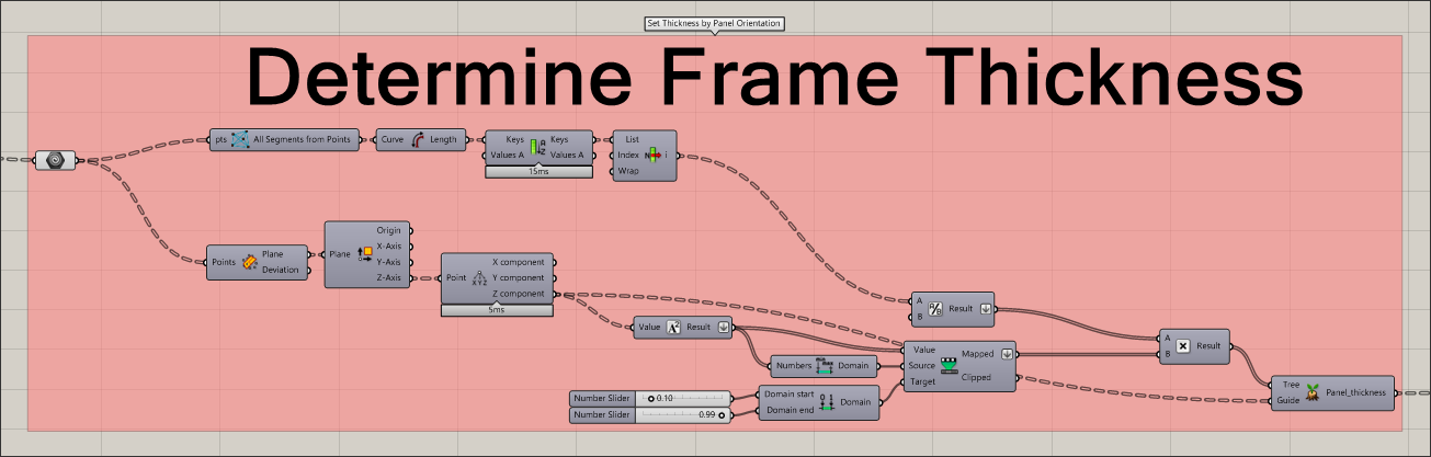
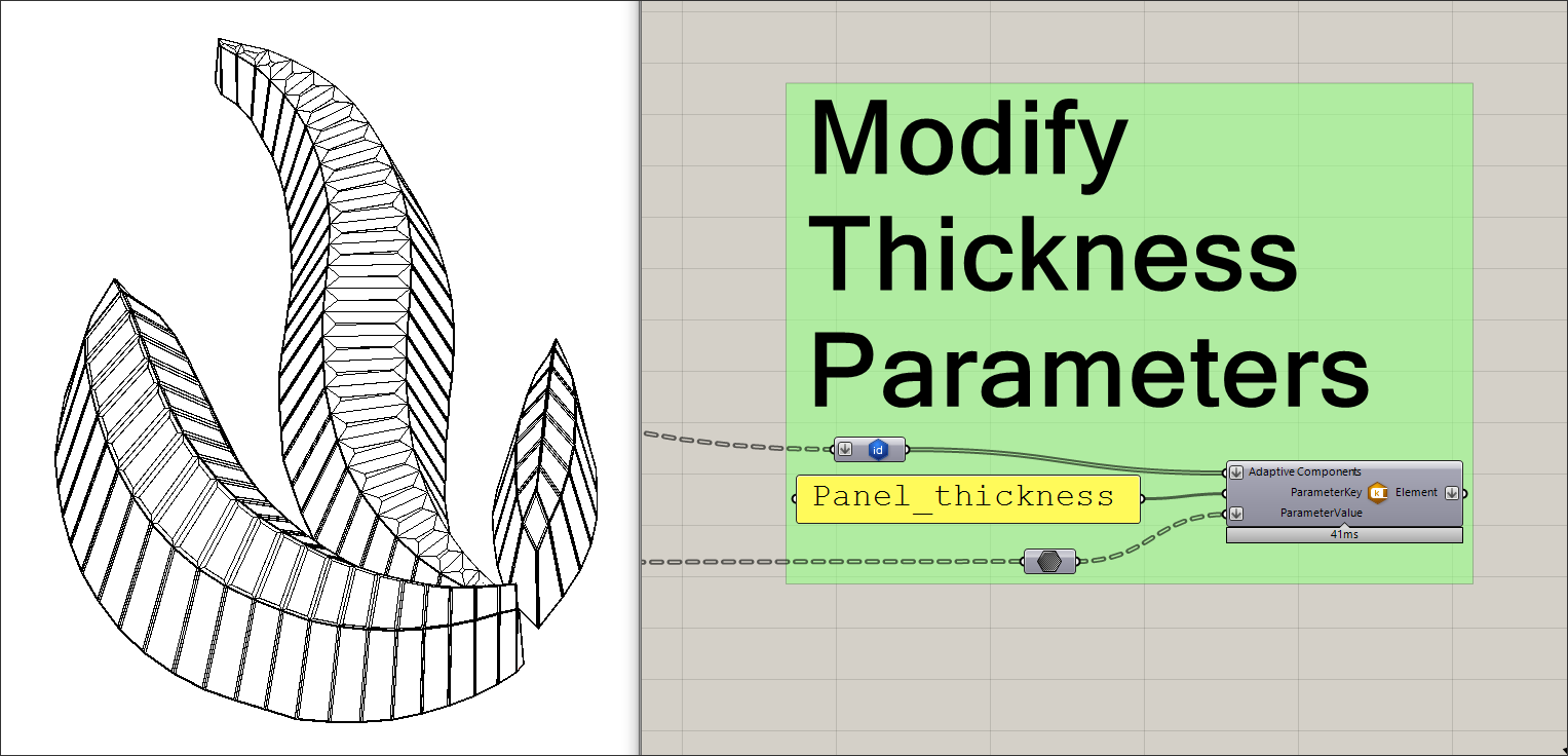
Let’s assume we want the thickness to depend on the orientation of the panel. If more vertical, then the frame thickness will be smaller, and the glass panel will be larger; more closed if horizontal. The definition below takes in the points and determines a thickness, with maximum thickness determined by half of the smallest line segment in the panel. The output will drive the new value of the parameter Panel_thickness.
The RiR component Set Element Parameter requires three (3) inputs:
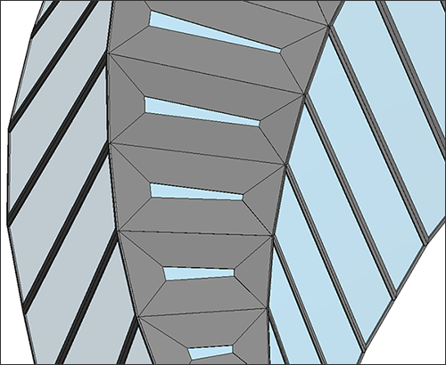
Connecting the calculated Panel_thickness parameters above, and the previously created instances of the Adaptive Component, the parameters can be modified with Set Element Parameter. Horizontal panels across the top of the middle structure are oriented more horizontally, and thus shown nearly closed.
With the panel thickness adjustable down to each instance, it gives granular control over the output, which was specified in the Parameter when it was created within the Adaptive Component.
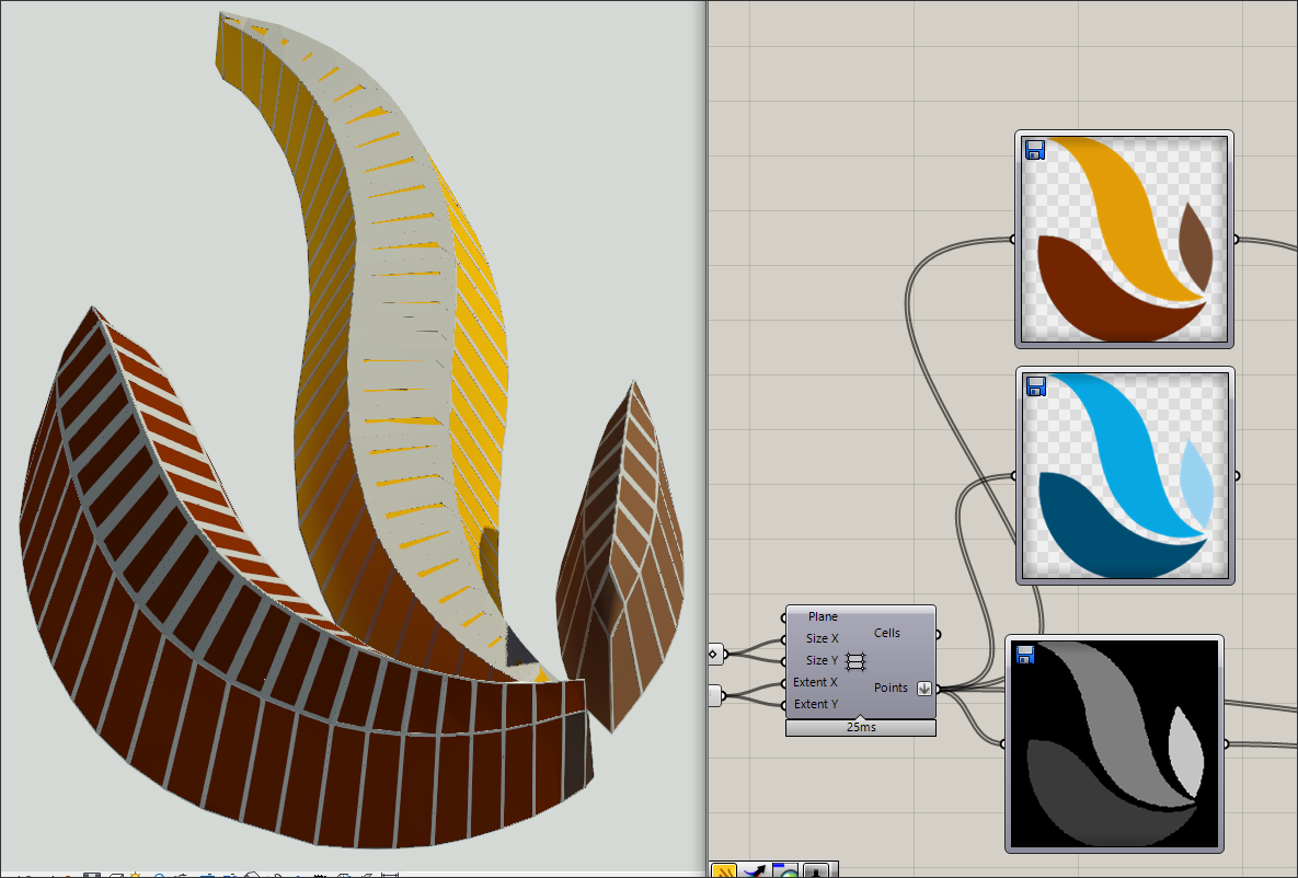
Now, if we rewind back to when we extracted the RGB values from the image, we can prepare the data to modify the Material Parameter Glass_panel.

By comparing the pixel color in the image to the location of the panel, RGB colors can be assigned to panels. These RGB values are then used to create names for Material Assets that will have distinct colors. In this case, there are a total of seven (7) distinct colors, so seven different Assets and Colors will be created. These are all Grasshopper Components.
Note: Technically, there are seven distinct colors detected by the Image Sampler, but this could reasonably be reduced to three (3) without changing the appearance too much. Sometime high precision is necessary, but similar to Significant Figures from Mathematics, it may be prudent to rationalize or round values so that custom fabrication costs are reduced.

These names and colors are connected to RiR components Create Appearance Asset and Create Material. This creates seven new Materials and Appearance Assets, duplicated from the specified template material: Glass. The color is connected to the Color and Tint Color inputs for Create Appearance Asset.

In the component Modify Material Assets, the newly created Assets and Materials are fed in so that the default Assets for Glass are swapped out for the new Assets. There is a lot going on in the background to make this happen.
Finally, with Set Element Parameter and connecting the 1) Adaptive Components, 2) Parameter Key (Glass_mat), and 3) New Material Assignments, the Materials will be applied to each instance parameter, all originally driven by the pixel color in the image.

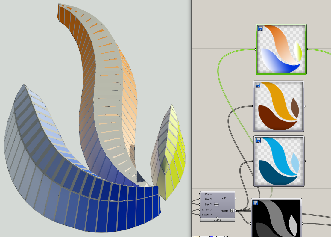
These colors can be changed later with ease simply by swapping the original image that was driving Material RGB values.
Or apply a gradient of colors across all of the panels!
This workflow is meant to demonstrate how BIM objects can be generatively designed in Revit, with the wealth of tools available in Rhino and Grasshopper. Rhino’s Geometry engine enables the creation of complex geometries, such as Non-Uniform Rational B-splines (NURBS) that would be impossible or very time-consuming to replicate in Revit, but easy with Rhino.Inside Revit.
Beyond the base functionality of Rhino+GH, Food4Rhino is a great resource for free and paid plugins for Rhino and Grasshopper, and what has been presented in this article is just the edge of what is possible. Image processing can allow for a hand-drawn sketch to drive the creation of BIM objects, and audio processing can allow sound and music to drive parameters. This tool has the potential to revolutionize how designers generate and engage with Building Information Models; find your inspiration and let it flow!
 Joseph Freund is an AEC Applications Specialist at Microsol Resources. He has a B.S. Degree in Electromechanical Engineering, and a Master of Architecture from Iowa State University. In his free time, he loves camping under dark skies and taking photos of nature.
AECbytes content should not be reproduced on any other website, blog, print publication, or newsletter without permission.
This article explores the new Rhino.Inside Revit add-in, which allows Rhino and Grasshopper to be used for design scripting in Revit as an alternative to Dynamo. It also takes a broader look at the area of design scripting in AEC, particularly in other BIM applications.
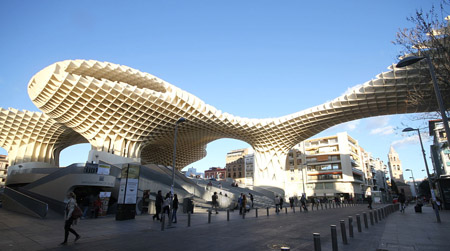
Mark Loomis shows how to use a Grasshopper script to model a waffle structure, using its algorithmic design capabilities to automate the process and allow parameters to be adjusted just by moving a number slider.
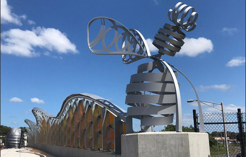
The “Beehive Bridge” is a 265-foot-long highway overpass in the city of New Britain, Connecticut, connecting the two parts of the city that are divided by a highway. Svigals + Partners, an architecture, art and advisory firm describes the implementation of AEC technology on this project.

ArchiCAD's Morph Tool can be used to create freeform elements. It is also a powerful early design tool for massing studies and for creating custom objects. This tutorial shows how it works and how it can be used to create a custom shape in ArchiCAD.